Chapter: Mechanical : Metrology and Measurements : Linear and Angular Measurements
Bevel protractors
BEVEL PROTRACTORS
Bevel
protractors are nothing but angular measuring instruments.
Types
of bevel protractors:
The different types of
bevel protractors used are:
1) Vernier
bevel protractor
2) Universal
protractor
3) Optical
protractor
VERNIER BEVEL
PROTRACTOR:
Working principle
A vernier bevel
protractor is attached with acute angle attachment. The body is designed its
back is flat and no projections beyond its back. The base plate is attached to
the main body and an adjustable blade is
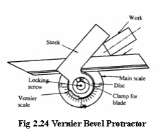
attached to the
circular plate containing Vernier scale. The main scale is graduated in degrees
from 0┬░ to 90┬░ in both the directions. The adjustable can be made to rotate
freely about the center of the main scale and it can be locked at any position.
For measuring acute angle, a special attachment is provided. The base plate is
made fiat for measuring angles and can be moved throughout its length. The ends
of the blade are beveled at angles of 45┬░ and 60┬░. The main scale is graduated
as one main scale division is 1┬░ and Vernier is graduated into 12 divisions on
each side of zero. Therefore the least count is calculated as
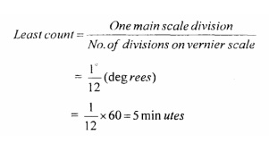
Thus, the bevel
protractor can be used to measure to an accuracy of 5 minutes.
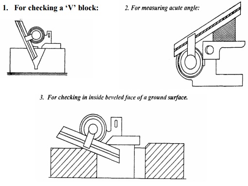
Applications of bevel protractor
The bevel protractor can be used in the following
applications.
AUTO- COLLIMATOR
Auto-collimator is an
optical instrument used for the measurement of small angular differences,
changes or deflection, plane surface inspection etc. For small angular
measurements, autocollimator provides a very sensitive and accurate approach.
An auto-collimator is essentially an infinity telescope and a collimator
combined into one instrument.
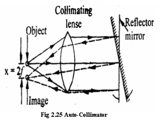
Basic
principle
If a light source is
placed in the flows of a collimating lens, it is projected as a parallel beam
of light. If this beam is made to strike a plane reflector, kept normal to the
optical axis, it is reflected back along its own path and is brought to the
same focus. The reflector is tilted through a small angle ŌĆś0ŌĆÖ. Then
beam the is deflected parallel twice the angle and is brought to focus in the same
plane as the light source.
The distance of focus
from the object is given by

WORKING
OF AUTO-COLLIMATOR:
There
are three main parts in auto-collimator.
1. Micrometer
microscope.
2. Lighting
unit and
3. Collimating
lens.
Figure shows a line
diagram of a modern auto-collimator. A target graticule is positioned
perpendicular to the optical axis. When the target graticule is illuminated by
a lamp, rays of light diverging from the intersection point reach the objective
lens via beam splitter. From objective, the light rays are projected as a
parallel rays to the reflector.
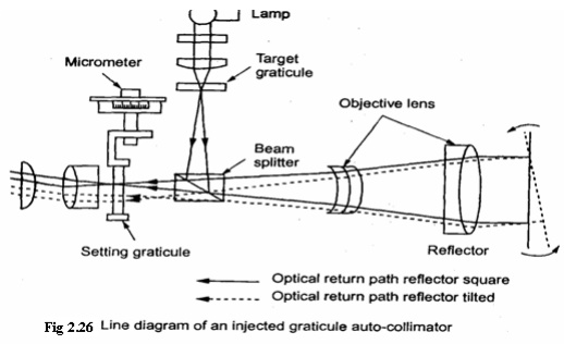
A flat reflector placed in front of the objective
and exactly normal to the optical axis reflects the parallel rays of light back
along their original paths. They are then brought to the target graticule and
exactly coincide with its intersection. A portion of the returned light passes
through the beam splitter and is visible through the eyepiece. If the reflector
is tilted through a small angle, the reflected beam will be changed its path at
twice the angle. It can also be brought to target graticule but linearly
displaced from the actual target by the amount 2╬Ėx
f. linear displacement of the graticule image in the plane tilted angle of
eyepiece is directly proportional to the reflector. This can be measured by
optical micrometer. The photoelectric auto- collimator is particularly suitable
for calibrating polygons, for checking angular indexing and for checking small
linear displacements.
APPLICATIONS
OF AUTO-COLLIMATOR
Auto-collimators
are used for
1) Measuring
the difference in height of length standards.
2) Checking
the flatness and straightness of surfaces.
3) Checking
square ness of two surfaces.
4) Precise
angular indexing in conjunction with polygons.
5) Checking
alignment or parallelism.
6) Comparative
measurement using master angles.
7) Measurement
of small linear dimensions.
8) For
machine tool adjustment testing.
Related Topics