Chapter: Satellite Communication : Earth Segment
Antenna Systems
Antenna Systems
:
The
antenna system consist of
Feed System
Antenna Reflector
Mount
Antenna tracking System
1. FEED SYSTEM
The
feed along with the reflector is the radiating/receiving element of
electromagnetic waves. The reciprocity property of the feed element makes the
earth station antenna system suitable for transmission and reception of
electromagnetic waves.
The
way the waves coming in and going out is called feed configuration
Earth
Station feed systems most commonly used in satellite communication are:
i)Axi-Symmetric
Configuration
ii)Asymmetric
Configuration
i)Axi-Symmetric
Configuration
In
an axi-symmetric configuration the antenna axes are symmetrical with respect to
the reflector ,which results in a relatively simple mechanical structure and
antenna mount.
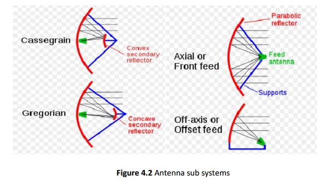
Primary Feed :
In
primary, feed is located at the focal point of the parabolic reflector. Many dishes use only a single bounce, with
incoming waves reflecting off the dish surface to the focus in front of the
dish, where the antenna is located. when the dish is used to transmit ,the
transmitting antenna at the focus beams waves toward the dish, bouncing them
off to space. This is the simplest arrangement.
Cassegrain :
Many
dishes have the waves make more than one bounce .This is generally called as folded
systems. The advantage is that the whole dish and feed system is more compact.
There are several folded configurations, but all have at least one secondary
reflector also called a sub reflector, located out in front of the dish to
redirect the waves.
A
common dual reflector antenna called Cassegrain has a convex sub reflector positioned in front of the main
dish, closer to the dish than the focus.
This
sub reflector bounces back the waves back toward a feed located on the main
dish’s center, sometimes behind a hole at the center of the main dish.
Sometimes
there are even more sub reflectors behind the dish to direct the waves to the
fed for convenience or compactness.
Gregorian
This
system has a concave secondary reflector located just beyond the primary focus.
This also bounces the waves back toward the dish.
ii)Asymmetric Configuration
Offset or Off-axis feed
The
performance of tan axi-symmetric configuration is affected by the blockage of
the aperture by the feed and the sub reflector assembly. The result is a
reduction in the antenna efficiency and an increase in the side lobe levels.
The asymmetric configuration can remove this limitation..This is achieved by
off- setting the mounting arrangement of the feed so that it does not obstruct the
main beam.As a result ,the efficiency and side lobe level performance are
improved.
2. ANTENNA
REFLECTOR :
Mostly
parabolic reflectors are used as the main antenna for the earth stations
because of the high gain available from the reflector and the ability of
focusing a parallel beam into a point at the focus where the feed,i.e., the
receiving/radiating element is located .For large antenna system more than one
reflector surfaces may be used in as in the cassegrain antenna system.
Earth
stations are also classified on the basis of services for example:
1.Two
way TV ,Telephony and data
2.
Two way TV
3.TV
receive only and two way telephony and data
4.Two
way data
From
the classifications it is obvious that the technology of earth station will
vary considerably on the performance and the service requirements of earth
station
For
mechanical design of parabolic reflector the following parameters are required
to be considered:
Size of the reflector
Focal Length /diameter ratio
RMS error of main and sub reflector
Pointing and tracking accuracies
Speed and acceleration
Type of mount
Coverage Requirement
Wind Speeed
The
size of the reflector depends on transmit and receive gain requirement and
beamwidth of the antenna.Gain is directly proportional to the antenna diameter
whereas the beamwidth is inversely proportional to the antenna diameter .for
high inclination angle of the satellite ,the tracking of the earth station
becomes necessary when the beamwidth is too narrow.
The
gain of the antenna is given by
Gain=
(η4ΠAeff)/ λ2
Where
Aeff is the aperture
Λ
is wave length
Η
is efficiency of antenna system
For
a parabolic antenna with circular aperture diameter D, the gain of the antenna
is :
Gain=
(η4Π/ λ2)( ΠD2/4)
=
η (ΠD/ λ)2
The
overall efficiency of the antenna is the net product of various factors such as
1.
Cross Polarization
2.
Spill over
3.
Diffraction
4.
Blockage
5.
Surface accuracy
6.
Phase error
7.
Illumination
In
the design of feed ,the ratio of focal length F to the diameter of the
reflector D of the antenna system control the maximum angle subtended by the
reflector surface on the focal point. Larger the F/D ratio larger is the
aperture illumination efficiency and lower the cross polarization.
3. ANTENNA
MOUNT:
Type
of antenna mount is determined mainly by the coverage requirement and tracking
requirements of the antenna systems. Different types of mounts used for earth
station antenna are:
i)
The Azimuth –elevation mount :
This
mount consists of a primary vertical axis. Rotation around this axis controls
the azimuth angle. The horizontal axis is mounted over the primary axis,
providing the elevation angle control.
ii)
The X-Y mount.
It
consists of a horizontal primary axis (X-axis) and a secondary axis (Y- axis)
and at right angles to it. Movement around these axes provides necessary
steering.
4. ANTENNA
TRACKING SYSTEM :
Tracking
is essential when the satellite drift, as seen by an earth station antenna is a
significant fraction of an earth station’s antenna beam width.
An
earth station’s tracking system is required to perform some of the functions
such as
i)Satellite
acquisition
ii)Automatic
tracking
iii)Manual
tracking
iv)Program
tracking.
Recent Tracking Techniques:
There
have been some interesting recent developments in auto-track techniques which
can potentially provide high accuracies at a low cost.
In
one proposed technique the sequential lobing technique has been I implemented
by using rapid electronic switching of a s single beam which effectively
approximates simultaneous lobbing.
Related Topics