Chapter: Mechanical : Gas Dynamics and Jet Propulsion : Jet Propulsion
The Turbofan Engine
The
Turbofan Engine
The
turboprop is limited to mach number of about 0.7 because of the sharp decrease
in propeller efficiency encountered above that mach number. However, the
turboprop concept of increasing mass
flow rate without
producing an excessive increment in exhaust velocity is valid
at any mach number and the use of a ducted fan combined with a jet turbine provides more economical operation at
mach numbers close to unity than does the simple jet turbine. If a duct or
shroud is placed around a jet engine and air is pumped through the annular
passage by means of one or more sets of compressor blades, the resulting engine
is called a turbofan, and is capable of producing (under proper conditions)
somewhat better thrust specific fuel consumption characteristics than the
turbojet itself. Basically, the air passing through the fan bypasses the
combustion process but has energy added to it by the compressor fan, so that a
sizable mass flow can be shunted through the fan. The air which bypasses the
combustion process leaves the engine with a lower amount of internal energy and
a lower exhaust speed than the jet exhaust. Yet, the thrust is not decreased
since the turbofan can pump more air per unit time than a conventional jet at
subsonic speeds. Accordingly, the average exhaust velocity of the turbofan
(averaging the turbine flow and the bypass flow) can be made smaller at a given
flight speed than that of a comparable turbojet and greater efficiency can be
obtained. In turbofan engine the fan cannot be designed for all compressor
ratios which is efficient at all mach numbers, thus, the turbofan is efficient
over a rather limited range of speeds. Within this speed range, however, its
improved cruise economy makes it a desirable unit for jet transport aircraft.

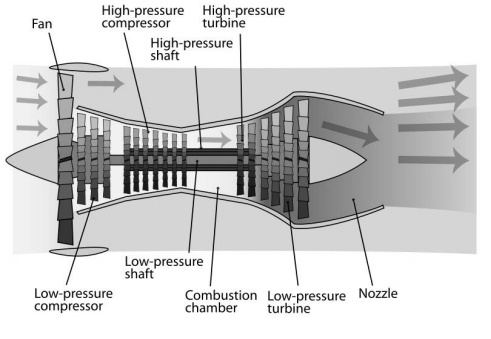
The turbofan engine has
a duct enclosed fan mounted at the front or rear of the engine and driven
either mechanically geared down or at the same speed as the compressor, or by
an independent turbine located to the rear of the compressor drive turbine
(Ref. Figure 7). There are two methods of handling the fan air. Either the fan
can exit separately from the primary engine air, or it can be ducted back to
mix with the primary engine’s air at the rear. If the fan air is ducted to the
rear, the total fan pressure must be higher than the static pressure in the
primary engine’s exhaust, or air will not flow. Similarly, the static fan
discharge pressure must be less than the total pressure the primary engine’s
exhaust, or the turbine will not be able to extract the energy required to
drive the compressor and fan. By closing down the area of flow of the fan duct,
the static pressure can be reduced and the dynamic pressure is increased.
The efficiency of the
fan engine is increased over that of the pure jet by converting more of the
fuel energy into pressure energy rather than the kinetic energy of a high
velocity exhaust gas stream. The fan produces additional force or thrust
without increasing fuel flow. As in the turboprop primary engine exhaust gas
velocities and pressures are low because of the extra turbine stages needed to
drive the fan, and as a result this makes the turbofan engine much quieter. One
fundamental difference between the turbofan and the turboprop engine is that
the air flow through the fan is controlled by design so that the air velocity
relative to the fan blades is unaffected by the aircraft’s speed. This
eliminates the loss in operational efficiency at high air speeds which limits
the maximum air speed of propeller driven aircraft.
Fan engines show a
definite superiority over the pure jet engines at speeds below Mach 1. The
increased frontal area of the fan presents a problem for high- speed aircraft
which, of course require small frontal areas. At high speeds air can be offset
at least partially by burning fuel in the fan discharge air. This would expand
the gas, and in order to keep the fan discharge air at the same pressure, the
area of the fan jet nozzle is increased. This action results in an increase in
gross thrust due to an increase in pressure times an area (PA), and an increase
in gross thrust specific fuel consumption.
Nozzle and diffuser
efficiencies
In ideal case, flow
through nozzle and diffuser is isentropic. But in actual case, friction exists
and affects in following ways:
i) Reduces the enthalpy drop reduces the
final velocity of steam iii) Increases the final dryness fraction iv) Increases
specific volume of the fluid v) Decreases the mass flow rate
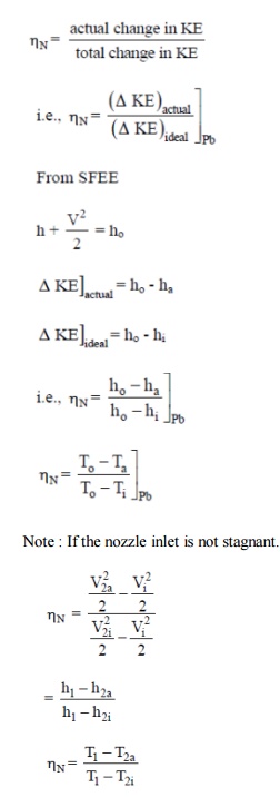
Nozzle performance
The isentropic operating conditions are very easy to
determine. Frictional losses in the nozzle can be accounted by several methods.
(1)
Direct information on the entropy change could be given although this is
usually not available.
(2)
Some times equivalents information is provided in the form of stagnation
pressure ratio. Normally nozzle performance is indicated by efficiency
parameter defined as
Related Topics