Chapter: Physics : Electromagnetic Waves and Wave optics : Higher Secondary(12 Std)
Superposition principle
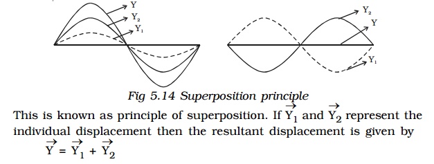
Superposition principle
When two or more waves simultaneously pass through the same medium, each wave acts on every particle of the medium, as if the other waves are not present. The resultant displacement of any particle is the vector addition of the displacements due to the individual waves.
1. Coherent sources
Two sources are said to be coherent if they emit light waves of the same wave length and start with same phase or have a constant phase difference.
Two independent monochromatic sources, emit waves of same wave length. But the waves are not in phase. So they are not coherent. This is because, atoms cannot emit light waves in same phase and these sources are said to be incoherent sources.
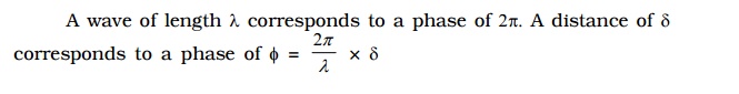
2. Phase difference and path difference
3. Interference of light
Two slits A and B illuminated by a single monochromatic source S act as coherent sources. The waves from these two coherent sources travel in the same medium and superpose at various points as shown in Fig. 5.15. The crest of the wavetrains are shown by thick continuous lines and troughs are shown by broken lines. At points where the crest of one wave meets the crest of the other wave or the trough of one wave meets the trough of the other wave, the waves are in phase, the displacement is maximum and these points appear bright. These points are marked by crosses (x). This type of interference is said to be constructive interference.
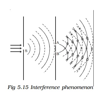
At points where the crest of one wave meets the trough of the other wave, the waves are in opposite phase, the displacement is minimum and these points appear dark. These points are marked by circles (O). This type of interference is said to be destructive interference. Therefore, on a screen XY the intensity of light will be alternatively maximum and minimum i.e. bright and dark bands which are referred as interference fringes. The redistribution of intensity of light on account of the superposition of two waves is called interference.
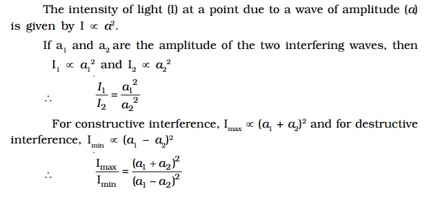
If a1 and a2 are the amplitude of the two interfering waves, then
4. Condition for sustained interference
The interference pattern in which the positions of maximum and minimum intensity of light remain fixed with time, is called sustained or permanent interference pattern. The conditions for the formation of sustained interference may be stated as :
1. The two sources should be coherent
2. Two sources should be very narrow
3. The sources should lie very close to each other to form distinct and broad fringes.
5. Young’s double slit experiment
The phenomenon of interference was first observed and demonstrated by Thomas Young in 1801. The experimental set up is shown in Fig 5.16.
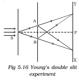
Light from a narrow slit S, illuminated by a monochromatic source, is allowed to fall on two narrow slits A and B placed very close to each other. The width of each slit is about 0.03 mm and they are about 0.3 mm apart. Since A and B are equidistant from S, light waves from S reach A and B in phase. So A and B act as coherent sources.
According to Huygen’s principle, wavelets from A and B spread out and overlapping takes place to the right side of AB. When a screen XY is placed at a distance of about 1 metre from the slits, equally spaced alternate bright and dark fringes appear on the screen. These are called interference fringes or bands. Using an eyepiece the fringes can be seen directly. At P on the screen, waves from A and B travel equal distances and arrive in phase. These two waves constructively interfere and bright fringe is observed at P. This is called central bright fringe.
When one of the slits is covered, the fringes disappear and there is uniform illumination on the screen. This shows clearly that the bands are due to interference.
6. Expression for bandwidth
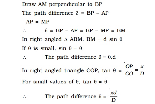
Let d be the distance between two coherent sources A and B of wavelength λ. A screen XY is placed parallel to AB at a distance D from the coherent sources. C is the mid point of AB. O is a point on the screen equidistant from A and B. P is a point at a distance x from O, as shown in Fig 5.17. Waves from A and B meet at P in phase or out of phase depending upon the path difference between two waves.
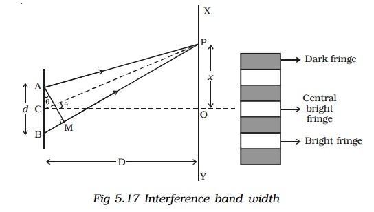
Bright fringes
By the principle of interference, condition for constructive interference is the path difference = nλ
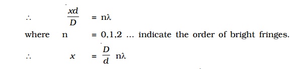
This equation gives the distance of the nth bright fringe from the point O.
Dark fringes
By the principle of interference, condition for destructive interference is the path difference
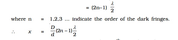
This equation gives the distance of the nth dark fringe from the point O. Thus, on the screen alternate dark and bright bands are seen on either side of the central bright band.
Band width (β)
The distance between any two consecutive bright or dark bands is called bandwidth.
The distance between (n+1)th and nth order consecutive bright fringes from O is given by
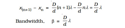
Similarly, it can be proved that the distance between two consecutive dark bands is also equal to Dλ/d. . Since bright and dark fringes are of same width, they are equi−spaced on either side of central maximum.
Condition for obtaining clear and broad interference bands
1. The screen should be as far away from the source as possible.
2. The wavelength of light used must be larger.
3. The two coherent sources must be as close as possible.
7. Colours of thin films
Everyone is familiar with the brilliant colours exhibited by a thin oil film spread on the surface of water and also by a soap bubble. These colours are due to interference between light waves reflected from the top and the bottom surfaces of thin films. When white light is incident on a thin film, the film appears coloured and the colour depends upon the thickness of the film and also the angle of incidence of the light.
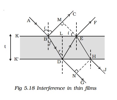
Interference in thin films
Consider a transparent thin film of uniform thickness t and its refractive index µ bounded by two plane surfaces K and K′ (Fig 5.18).
A ray of monochromatic light AB incident on the surface K of the film is partly reflected along BC and partly refracted into the film along BD. At the point D on the surface K′, the ray of light is partly reflected along DE and partly transmitted out of the film along DG. The reflected light then emerges into air along EF which is parallel to BC. The ray EH after refraction at H, finally emerges along HJ.
BC and EF are reflected rays parallel to each other and DG and HJ are transmitted rays parallel to each other. Rays BC and EF interfere and similarly the rays DG and HJ interfere.
Interference due to the reflected beam
EM is drawn normal to BC from E. Now the path difference between the waves BC and EF
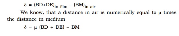
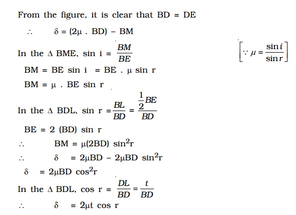
A ray of light travelling in air and getting reflected at the surface of a denser medium, undergoes an automatic phase change of π (or) an additional path difference of λ/2.
Since the reflection at B is at the surface of a denser medium, there is an additional path difference λ/2.
Interference due to the transmitted light
The path difference between the transmitted rays DG and HJ is, in a similar way, δ = 2µt cos r. In this case there is no additional path difference introduced because both reflections at the point D and E take place backed by rarer medium
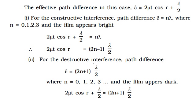
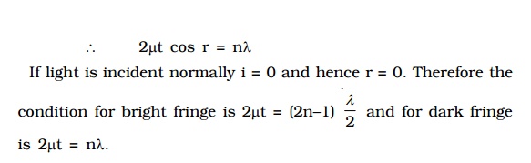
Hence, condition for brightness is 2 µt cos r = nλ and condition for darkness is 2µt cos r = (2n – 1) λ/2.
8. Newton’s rings
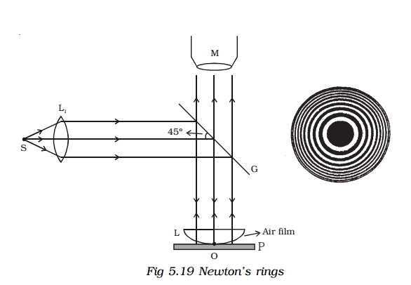
An important application of interference in thin films is the formation of Newton’s rings. When a plano convex lens of long focal length is placed over an optically plane glass plate, a thin air film with varying thickness is enclosed between them. The thickness of the air film is zero at the point of contact and gradually increases outwards from the point of contact. When the air film is illuminated by monochromatic light normally, alternate bright and dark concentric circular rings are formed with dark spot at the centre. These rings are known as Newton’s rings. When viewed with white light, the fringes are coloured (shown in the wrapper of the text book).
Experiment
Fig 5.19 shows an experimental arrangement for producing and observing Newton’s rings. A monochromatic source of light S is kept at the focus of a condensing lens L1. The parallel beam of light emerging from L1 falls on the glass plate G kept at 45o. The glass plate reflects a part of the incident light vertically downwards, normally on the thin air film, enclosed by the plano convex lens L and plane glass plate P. The reflected beam from the air film is viewed with a microscope. Alternate bright and dark circular rings with dark spot as centre is seen.
Theory
The formation of Newton’s rings can be explained on the basis of interference between waves which are partially reflected from the top and bottom surfaces of the air film. If t is the thickness of the air film at a point on the film, the refracted wavelet from the lens has to travel a distance tinto the film and after reflection from the top surface of the glass plate, has to travel the same distance back to reach the point again.
Thus, it travels a total path 2t. One of the two reflections takes place at the surface of the denser medium and hence it introduces an additional phase change of π or an equivalent path difference λ/2 between two wavelets.
∴ The condition for brightness is, Path difference,
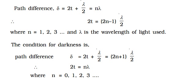
The thickness of the air film at the point of contact of lens L with glass plate P is zero. Hence, there is no path difference between the interfering waves. So, it should appear bright. But the wave reflected from the denser glass plate has suffered a phase change of π while the wave reflected at the spherical surface of the lens has not suffered any phase change. Hence the point O appears dark. Around the point of contact alternate bright and dark rings are formed.
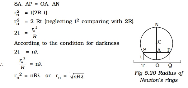
9. Expression for the radius of the nth dark ring
Let us consider the vertical section SOP of the plano convex lens through its centre of curvature C, as shown in Fig 5.20. Let R be the radius of curvature of the plano convex lens and O be the point of contact of the lens with the plane surface. Let t be the thickness of the air film at S and P. Draw ST and PQ perpendiculars to the plane surface of the glass plate. Then ST = AO = PQ = t
Let rn be the radius of the nth dark ring which passes through the points S and P.
Then SA = AP = rn
If ON is the vertical diameter of the circle, then by the law of segments
10. Applications of Newtons rings
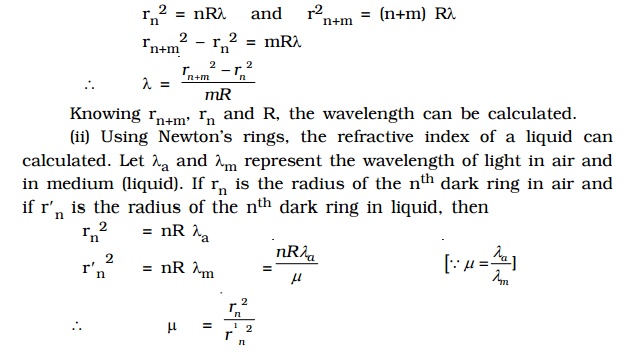
(i) Using the method of Newton’s rings, the wavelength of a given monochromatic source of light can be determined. The radius of nth dark ring and (n+m)th dark ring are given by
Related Topics