Chapter: Electronic Devices and Circuits : Transistors
Silicon Controlled Rectifier (SCR): Construction, Working Principle
SILICON CONTROLLED RECTIFIER (SCR)
Introduction
The SCR stand for Silicon Control Rectifier, it is used in industries because it can handle high values of current and voltage.
Three terminals
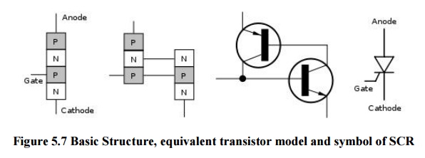
Anode - P-layer
Cathode - N-layer (opposite end)
Gate - P-layer near the cathode
Three junctions - four layers
Connect power such that the anode is positive with respect to the cathode - no current will flow
A silicon controlled rectifier is a semiconductor device that acts as a true electronic switch. It can change alternating current and at the same time can control the amount of power fed to the load. SCR combines the features of a rectifier and a transistor.

Ø Construction
When a pn junction is added to a junction transistor the resulting three pn junction device is called a SCR. ordinary rectifier (pn) and a junction transistor (npn) combined in one unit to form pnpn device.
Three terminals are taken : one from the outer p- type material called anode a second from the outer n- type material called cathode K and the third from the base of transistor called Gate. GSCR is a solid state equivalent of thyratron. The gate anode and cathode of SCR correspond to the grid plate and cathode of thyratron SCR is called thyristor.
Ø Working Principle
Load is connected in series with anode the anode is always kept at positive potential w.r.t cathode.
Ø SCR Operation / Working
The Silicon Control Rectifier SCR start conduction when it is forward biased. For this purpose the cathode is kept at negative and anode at positive. When positive clock pulse is applied at the gate the SCR turns ON.
When forward bias voltage is applied to the Silicon Control Rectifier SCR, the junction J1 and J3 become forward bias while the junction J2 become reverse bias.
When we apply a clock pulse at the gate terminal, the junction J= become forward bias and the Silicon Control Rectifier SCR start conduction.The Silicon Control Rectifier SCR turn ON and OFF very quickly, At the OFF state the Silicon Control Rectifier SCR provide infinity resistance and in ON state, it offers very low resistance, which is in the range of 0.01O to 1O.
Ø SCR Firing & Triggering
The Silicon Control Rectifier SCR is normally operated below the forward break over voltage (VBO). To turn ON the Silicon Control Rectifier SCR we apply clock pulse at the gate terminal which called triggering of Silicon Control Rectifier, but when the Silicon Control Rectifier SCR turned ON, now if we remove the triggering voltage, the Silicon Control Rectifier SCR will remain in ON state. This voltage is called Firing voltage.
Ø When Gate is Open
No voltage applied to the gate, j2 is reverse biased while j1 and j3 are FB . J1 and J3 is just in npn transistor with base open .no current flows through the load RL and SCR is cut off. If the applied voltage is gradually increased a stage is reached when RB junction J2 breakdown .the SCR now conducts heavily and is said to be ON state. the applied voltage at which SCR conducts heavily without gate voltage is called Break over Voltage.
Ø When Gate is Positive w.r.to Cathode:-
The SCR can be made to conduct heavily at smaller applied voltage by applying small positive potential to the gate.J3 is FB and J2 is RB the electron from n type material start moving across J3 towards left holes from p type toward right. Electrons from j3 are attracted across junction J2 and gate current starts flowing. as soon as gate current flows anode current increases. the increased anode current in turn makes more electrons available at J2breakdown and SCR starts conducting heavily. the gate loses all control if the gate voltage is removed anode current does not decrease at all. The only way to stop conduction is to reduce the applied voltage to zero.
Ø Break over Voltage
It is the minimum forward voltage gate being open at which SCR starts conducting heavily i.e turned on.
Ø Peak Reverse Voltage ( PRV)
It is the maximum reverse voltage applied to an SCR without conducting in the reverse direction.
Ø Holding Current
It is the maximum anode current gate being open at which SCR is turned off from on conditions.
Related Topics