Chapter: Power Electronics : Power Semi Conductor Devices
Series and parallel operation of SCR
Series and parallel operation of SCR
SCR are connected in series for h.v demand and in parallel for fulfilling high current demand. Sting efficiency can be defined as measure of the degree of utilization on SCRs in a string.
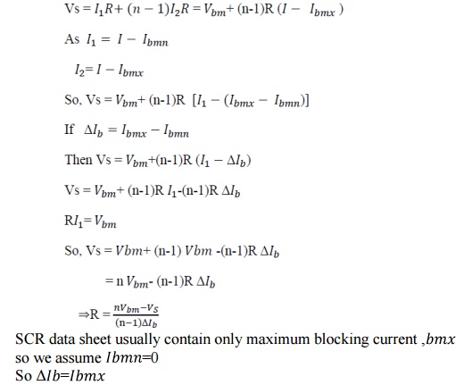
String efficiency < 1.
Derating factor (DRF) 1 – string efficiency.
If DRF more then no. of SCRs will more, so string is more reliable.
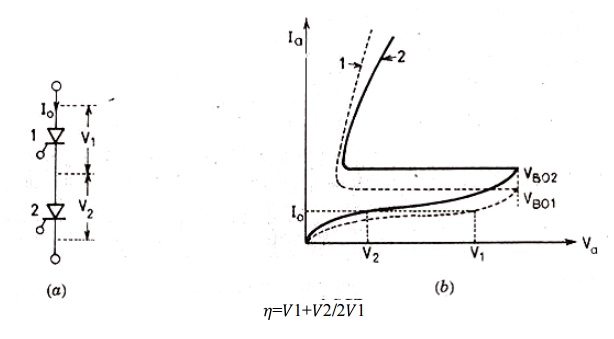
Let the rated blocking voltage of the string of a series connected SCR is 2V1 as shown in the figure below, But in the string two SCRs are supplied a maximum voltage of
V1+V2.
Significance of string efficiency .
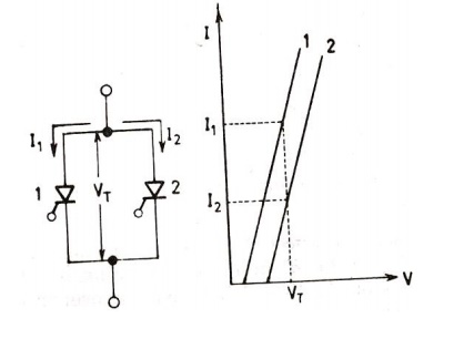
Two SCRs are have same forward blocking voltage ,When system voltage is more then the voltage rating of a single SCR. SCRs are connected in series in a string. There is a inherent variation in characteristics. So voltage shared by each SCR may not be equal. Suppose, SCR1 leakage resistance > SCR2 leakage resistance. For same leakage current I0 in the series connected SCRs. For same leakage current SCR1 supports a voltage V1 , SCR2supports a voltage V2,
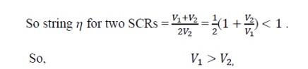
The above operation is when SCRs are not turned ON. But in steady state of operation , A uniform voltage distribution in the state can be achieved by connect a suitable resistance across each SCRs , so that parallel combination have same resistance. But this is a cumbersome work. During steady state operation we connect same value of shunt resistance across each SCRs. This shunt resistance is called state equalizing circuit.
Suppose,
Let SCR1 has lower leakage current I , It will block a voltage comparatively larger than other SCRs.
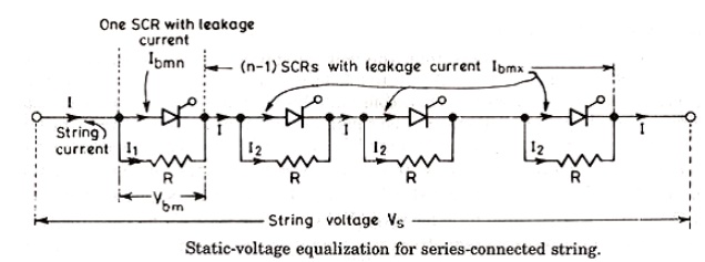
Voltage across SCR1 is Vbm = 1 . Voltage across (n-1)SCR is (n-1) I2R, so the voltage equation for the series circuit is
So the value of R calculated is low than actually required.
SCRs having unequal dynamic characteristics:
It may occur that SCRS may have unequal dynamic characteristics so the voltage distribution across the SCR may be unequal during the transient condition.
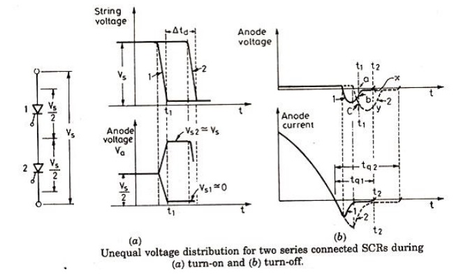
SCR 1 and SCR 2 have different dynamic characteristics. Turn ON time of SCR 2 is more than SCR 1 by time D. As string voltage is so voltage shared by each SCRs be Vs /2. Now both are gated at same time so SCR 1 will turn ON at t1 its voltage fall nearly to zero so the voltage shared by SCR 2 will be the string voltage if the break over voltage of SCR 2 is less than Vs then SCR 2 will turn ON .
* In case is less than the breakoverer voltage, SCR 2 will turn ON at instant 2. SCR 1 assumed to have less turn off tq1 time then SCR 2, so tq1< tq2 . At t2 SCR 1 has recovered while SCR 2 is developing recovery voltage at t1 both are developing different reverse recovery voltage. At t2 SCR 1 has recovered while SCR2 is developing reverse recovery voltage .
Conclusion :
* Series connected SCR develop different voltages during turn ON and turn OFF process. Till now we connect a simple resistor across the diode for static voltage equalizing circuit .
* During turn ON and turn OFF capacitance of reverse biased junction determine the voltage distribution across SCRs in a series connected string . As reverse biased junction have different capacitance called self capacitance, the voltage distribution during turn ON and turn Off process would be different.
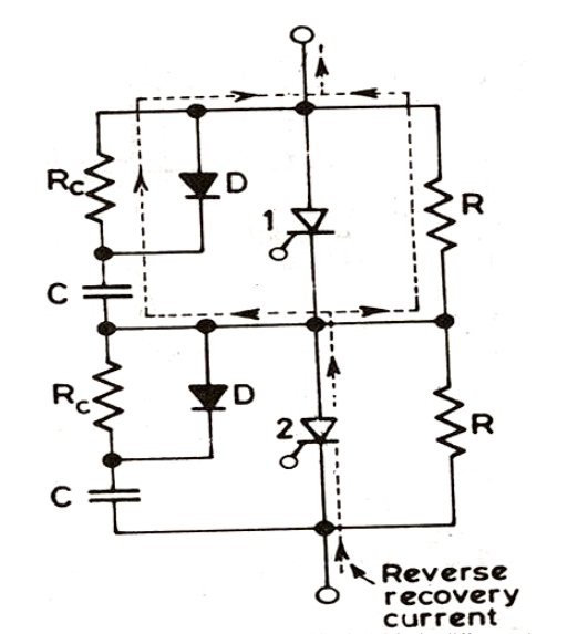
* Under transient condition equal voltage distribution can be achieved by employing shunt capacitance as this shunt capacitance has the effect of that the resultant of shunt and self capacitance tend to be equal. The capacitor is used to limits the dv/dt across the SCR during forward blocking state. When this SCR turned ON capacitor discharges heavy current through the SCR . The discharge current spike is limited by damping resistor . RC also damps out high frequency oscilation that may arise due to series combination of ,C and series inductor . RC & C are called dynamic equalizing circuit Diode D is used during forward biased condition for more effective charging of the capacitor. During capacitor discharge RC comes into action for limiting current spike and rate of change of current di/dt.
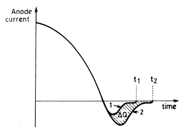
The R, RC & C component also provide path to flow reverse recovery current. When one SCR regain its voltage blocking capability. The flow of reverse recovery current is necessary as it facilitates the turning OFF process of series connected SCR string. So C is necessary for both during turn ON and turn OFF process. But the voltage unbalance during turn OFF time is more predominant then turn ON time. So choice of C is based on reverse recovery characteristic of SCR .
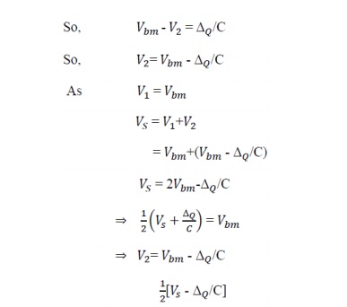
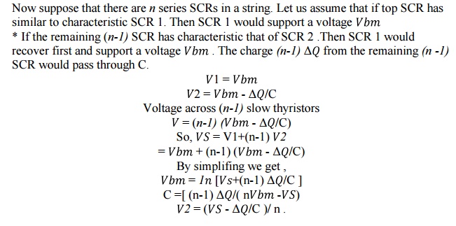
SCR 1 has short recovery time as compared to SCR 2. O is the difference in reverse recovery charges of two SCR 1 and SCR 2. Now we assume the SCR 1 recovers fast .i.e it goes into blocking state so charge Q can pass through C . The voltage induced by C1 1 is ΔQ/C ,where is no voltage induced across C2 . The difference in voltage to which the two shunt capacitor are charged is Δ Q/C .Now thyristor with least recovery time will share the highest transient voltage say Vbm,
Parallel operation of SCR:
When current required by the load is more than the rated current of single thyristor , SCRs are connected in parallel in a string .
Related Topics