Chapter: High Voltage Engineering : Over Voltages in Electrical Power Systems
Over Voltages Due to Switching surges
OVER VOLTAGES DUE TO SWITCHINGSURGES
The increase in transmission voltages needed to fulfill the required increase in transmitted powers, switching surges have become the governing factor in the design of insulation for EHV and UHV systems. In the meantime, lightning over voltages come as a secondary factor in these networks. There are two fundamental reasons for this shift in relative importance from lightning to switching surges as higher transmission voltages are called for:
· Overvoltages produced on transmission lines by lightning strokes are only slightly dependent on the power systemvoltages.As a result, their magnitudes relative to the system peak voltage decrease as the latter is increased.
· External insulation has its lowest breakdown strength under surges whose fronts fall in the range 50-500 micro sec.,which is typical for switching surges.
· According to the International Electro-technical Commission(IEC) recommendations, all equipment designed for operating voltages above 300 kV should be tested under switching impulses (i.e., laboratory-simulated switching surges).
Temporary over voltages
The purpose of this Guide is to provide information on transient and temporary over voltages and currents in end-user AC power systems. With this information in hand, equipment designers and users can more accurately evaluate their operating environment to determine the need for surge protective devices (SPDs) or other mitigation schemes. The Guide characterizes electrical transmission and distribution systems in which surges occur, based upon certain theoretical considerations as well as on the data that have been recorded in interior locations with particular emphasis on industrial environments. There are no specific mathematical models that simulate all surge environments; the complexities of the real world need to be simplified to produce a manageable set of standard surge tests. To this end, a scheme to classify the surge environment is presented.
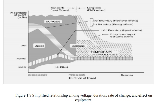
This classification provides a practical basis for the selection of surge-voltage and surge-current waveforms and amplitudes that can be applied to evaluate the capability of equipment to withstand surges when connected to power circuits. The fundamental approach to electromagnetic compatibility (EMC) in the arena of surges is the requirement that equipment immunity and characteristics of the surge environment characteristics should be properly coordinated. By definition, the duration of the surges considered in this Guide do not exceed a one-half period of the normal mains waveform. They can be periodic or random events and might appear in any combination of line, neutral, or grounding conductors. They include those surges with amplitudes, durations, or rates of change sufficient to cause equipment damage or operational upset (see Figure1.7). Surge protective devices acting primarily on the voltage are often applied to divert damaging surges, but the upset can require other remedies.
Temporary over voltages represent a threat to equipment as well as to any surge protective devices that may have been provided for the mitigation of surges. The scope of this Guide includes temporary over voltages only as a threat to the survival of SPDs, and therefore includes considerations on the selection of suitable SPDs. No equipment performance requirements are specified in this Guide. What is recommended is a rational, deliberate approach to recognizing the variables that need to be considered simultaneously, using the information presented here to define a set of representative situations. For specific applications, the designer has to take into consideration not only the rates of occurrence and the waveforms described in this Guide, but also the specific power system environment and the characteristics of the equipment in need of protection. As an example, the following considerations are necessary to reach the goal of practical surge immunity:
· Desired protection
· Hardware integrity
· Process immunity
· Specific equipment sensitivities
· The power environment
· Surge characteristics
· Electrical system
· Performance of surge protective devices
· Protection
· Lifetime
· The test environment
· Cost effectiveness
Answers may not exist that address all of the questions raised by the considerations listed above. In particular, those related to specific equipment sensitivities, both in terms of component failure and especially in terms of processing errors, might not be available to the designer. The goal of the reader may be simply selecting the most appropriate device from among the various surge protective devices available and meet the requirements of the equipment that they must protect. Subsets of the considerations in this section might then apply, and the goal of the reader may then be the testing of various surge protective devices under identical test conditions. The following can guide the reader in identifying parameters, seeking further facts, or quantifying a test plan.
Desired Level of Protection
The desired level of protection can vary greatly depending upon the application. For example, in applications not involving online performance, protection may only be needed to reduce hardware failures by a certain percentage. In other cases, such as data processing or critical medical or manufacturing processes, any interruption or upset of a process might be unacceptable. Hence, the designer should quantify the desired goal with regard to the separate questions of hardware failure and process interruption or upset.
Equipment Sensitivities
Specific equipment sensitivities should be defined in concert with the above-mentioned goals. The sensitivities (immunity) will be different for hardware failure or process upset. Such definitions might include: maximum amplitude and duration of the surge remnant that can be tolerated, wave-form or energy sensitivity, et cetera.
Power Environment
The applicable test waveforms recommended in this Guide should be quantified on the basis of the location categories and exposure levels as explained in the corresponding clauses of the Guide. The magnitude of the rams voltage, including any anticipated variation, should be quantified. Successful application of surge protective devices requires taking into consideration occasional abnormal occurrences. It is essential that an appropriate selection of the SPD limiting voltage is based on actual characteristics of the mains voltage.
Performance of Surge Protective Devices
Evaluation of a surge protective device should verify a long life in the presence of both the surge and electrical system environments described above. At the same time, its remnant and voltage levels should provide a margin below the immunity levels of the equipment in order to achieve the desired protection. It is essential to consider all of these parameters simultaneously. For example, the use of a protective device rated very close to the nominal system voltage might provide attractive remnant figures, but can be unacceptable when a broad range of occasional abnormal deviations in the amplitude of the mains waveform are considered. Lifetime or overall performance of the SPDs should not be sacrificed for the sake of a low remnant.
Test Environment
The surge test environment should be carefully engineered with regard to the preceding considerations and any other parameters that are important to the user. A typical description of the test-environment includes definitions of simultaneous voltages and currents, along with proper demonstrations of short-circuit.
It is important to recognize that the specification of an open-circuit voltage without simultaneous short-circuit current capability is meaningless. Cost Effectiveness The cost of surge protection can be small, compared to overall system cost and benefits in performance. Therefore, added quality and performance in surge protection may be chosen as a conservative engineering approach to compensate for unknown variables in the other parameters. This approach can provide excellent performance in the best interests of the user, while not significantly affecting overall system cost.
Definitions
The definitions given here have been developed by several standards-writing organizations and have been harmonized.
Back Flashover (Lightning):
A flashover of insulation resulting from a lightning strike to part of a network or electrical installation that is normally at ground potential. Blind Spot: A limited range within the total domain of application of a device, generally at values less than the maximum rating. Operation of the equipment or the protective device itself might fail in that limited range despite the device's demonstration of satisfactory performance at maximum ratings.
Clamping Voltage:
Deprecated term. See measured limiting voltage.
Combination Surge (Wave): A surge delivered by an instrument which has the inherent capability of applying a 1.2/50 us voltage wave across an open circuit, and delivering an 8/20 us current wave into a short circuit. The exact wave that is delivered is determined by the instantaneous impedance to which the combination surge is applied.
Combined Multi-Port Spd: A surge protective device integrated in a single package as the means of providing surge protection at two or more ports of a piece of equipment connected to different systems (such as a power system and a communications system).
Coordination Of Spds (Cascade):The selection of characteristics for two or more SPDs to be connected across the same conductors of a system but separated by some decoupling impedance such that, given the parameters of the impedance and of the impinging surge, this selection will ensure that the energy deposited in each of the SPDs is commensurate with its rating.
Direct Strike: A strike impacting the structure of interest or the soil (or objects) within a few meters from the structure of interest. Energy Deposition: The time integral of the power dissipated in a clamping-type surge protective device during a current surge of a specified waveform. Failure Mode: The process and consequences of device failure.
Leakage Current: Any current, including capacitive coupled currents, that can be conveyed from accessible parts of a product to ground or to other accessible parts of the product.
Lightning Protection System (LPS): The complete system used to protect a space against the effects of lightning. It consists of both external and internal lightning protection systems.
Lightning Flash To Earth: An electrical discharge of atmospheric origin between cloud and earth consisting of one or more strikes.
Lightning Strike: A single electrical discharge in a lightning flash to earth.
Mains: The AC power source available at the point of use in a facility. It consists of the set of electrical conductors (referred to by terms including service entrance, feeder, or branch circuit) for delivering power to connected loads at the utilization voltage level.
Maximum continuous operating voltage (MCOV): The maximum designated root-mean-square (rms) value of power-frequency voltage that may be applied continuously between the terminals of the arrester.
Measured limiting voltage: The maximum magnitude of voltage that appears across the terminals of the SPD during the application of an impulse of specified wave shape and amplitude.
Nearby strike: A strike occurring in the vicinity of the structure of interest.
Nominal System Voltage: A nominal value assigned to designate a system of a given voltage class.
Nominal Arrestor voltage: The voltage across the arrestor measured at a specified pulsed DC current, IN(dc), of specific duration. IN(dc) is specified by the arrestor manufacturer.
One-Port SPD: An SPD having provisions (terminals, leads, plug) for connection to the AC power circuit but no provisions (terminals, leads, receptacles) for supplying current to the AC power loads.
Open-circuit voltage (OCV) :The voltage available from the test set up (surge generator, coupling circuit, back filter, connecting leads) at the terminals where the SPD under test will be connected.
Point of strike: The point where a lightning strike contacts the earth, a structure, or an
LPS.
Pulse life: The number of surges of specified voltage, current amplitudes, and wave shapes that may be applied to a device without causing degradation beyond specified limits. The pulse life applies to a device connected to an AC line of specified characteristics and for pulses sufficiently spaced in time to preclude the effects of cumulative heating.
Response time (arrestor): The time between the point at which the wave exceeds the limiting voltage level and the peak of the voltage overshoot. For the purpose of this definition, limiting voltage is defined with a 8/20 Its current waveform of the same peak Current amplitude as the waveform used for this response time.
Short-Circuit Current (Scc): The current which the test set up (surge generator, coupling circuit, back filter, connecting leads) can deliver at the terminals where the SPD under test will be connected, with the SPD replaced by bonding the two lead terminals. (Also sometimes abbreviated as SCI).
SPD disconnect or: A device for disconnecting an SPD from the system in the event of SPD failure. It is to prevent a persistent fault on the system and to give a visible indication of the SPD failure.
Surge Response Voltage: The voltage profile appearing at the output terminals of a protective device and applied to downstream loads, during and after a specified impinging surge, until normal stable conditions are reached.
Surge Protective device (SPD): A device that is intended to limit transient overvoltages and divert surge currents. It contains at least one nonlinear component—a surge reference equalizer. A surge protective device used for connecting equipment to external systems whereby all conductors connected to the protected load are routed—physically and electrically—through a single enclosure with a shared reference point between the input and output ports of each system.
Swell: A momentary increase in the power frequency voltage delivered by the mains, outside of the normal tolerances, with a duration of more than one cycle and less than a few seconds.
1. Switching Surge Test Voltage Characteristics
Switching surges assume great importance for designing insulation of overhead lines operating at voltages more than 345 kV. It has been observed that the flashover voltage for various geometrical arrangements under unidirectional switching surge voltages decreases with increasing the front duration of the surge and the minimum switching surge corresponds to the range between 100 and 500 ÎĽsec. However, time to half the value has no effect as flashover takes place either at the crest or before the crest of the switching surge. Fig.1.8 gives the relationship between the critical flashover voltage per meter as a function of time to flashover for on a 3 m rod-rod gap and a conductor-plane gap.
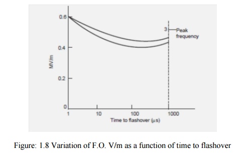
It can be seen that the standard impulse voltage (1/50 ÎĽ sec) gives highest flashover voltage and switching surge voltage with front time varying between 100 to 500 ÎĽ sec has lower flashover voltages compared to power frequency voltage. The flashover voltage not only depends upon the crest time but upon the gap spacing and humidity for the same crest time surges.
It has been observed that the switching surge voltage per meter gap length decreases drastically with increase in gap length and, therefore, for ultra high voltage system, costly design clearances are required. Therefore, it is important to know the behavior of external insulation with different configuration under positive switching surges as it has been found that for nearly all gap configurations which are of practical interest positive switching impulse is lower than the negative polarity switching impulse.
It has also been observed that if the humidity varies between 3 to 16 gm/m3, the breakdown voltage of positive and gaps increases approximately 1.7% for 1 gm/m3 increase in absolute humidity. For testing purposes the switching surge has been standardized with wave front time 250 ÎĽ deceit is known that the shape of the electrode has a decided effect on the flashover voltage of the insulation.
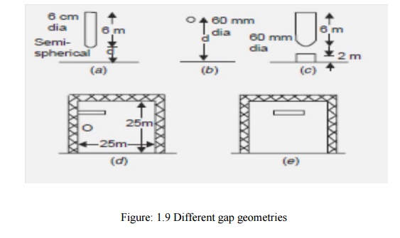
Lot of experimental work has been carried on the switching surge flash over voltage furlong gaps using rod-plane gap and it has been attempted to correlate these voltages with switching surge flash over voltage of other configuration electrodes. Several investigators have shown that if the gap length varies between 2 to 8 m, the 50% positive switching surge flash over for any configurations given by the expression
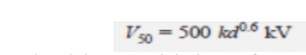
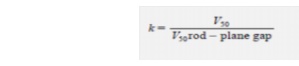
where d is the gap length in meters, k is the gap factor which is a function of electrode geometry. Forrod-plane gaps K = 1.0. Thus K represents a proportionality content and is equal to 50% flash overvoltage of any gap geometry to that of a rod-plane gap for the same gap spacing
i.e., The expression for V50 applies to switching impulse of constant crest time. A more general expression which applies to longer times to crest has been proposed as follows :

here K and d have the same meaning as in the equation above. The gap factor K depends mainly on the gap geometry and hence on the field distribution in the gap. Shown in Fig 1.9
2. Over voltage Protection
The causes of over voltages in the system have been studied extensively in previous sections. Basically, there are two sources: (i) external over voltages due to mainly lightning, and (ii) internal overvoltage mainly due to switching operation. The system can be protected against external over voltages using what are known as shielding methods which do not allow an arc path to form between the line conductors and ground, thereby giving inherent protection in the line design. For protection against internal voltages normally non-shielding methods are used which allow an arc path between the ground structure and the line conductor but means are provided to quench the arc. The use of ground wire is a shielding method whereas the use of spark gaps, and lightning arresters are the non-shielding methods. We will study first the non-shielding methods and then the shielding methods. However, the non shielding methods can also be used for external over voltages.
The non-shielding methods are based upon the principle of insulation breakdown as the Overvoltage is incident on the protective device; thereby a part of the energy content in the overvoltage is discharged to the ground through the protective device. The insulation breakdown is not only a function of voltage but it depends upon the time for which it is applied and also it depends upon the shape and size of the electrodes used.
The steeper the shape of the voltage wave, the larger will be the magnitude of voltage required for breakdown; this is because an expenditure of energy is required for the rupture of any dielectric, whether gaseous, liquid or solid, and energy involves time. The energy criterion for various insulations can be compared in terms of a common term known as Impulse Ratio which is defined as the ratio of breakdown voltage due to an impulse of specified shape to the breakdown voltage at power frequency. The impulse ratio for sphere gap is unity because this gap has a fairly uniform field and the breakdown takes place on the field ionization phenomenon mainly whereas for a needle gap it varies between 1.5 to 2.3 depending upon the frequency and gap length. This ratio is higher than unity because of the non-uniform field between the electrodes.
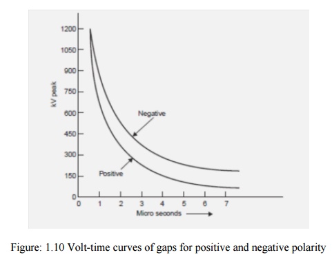
The impulse ratio of a gap of given geometry and dimension is greater with solid than with air dielectric. The insulators should have a high impulse ratio for an economic design whereas the lightning arresters should have a low impulse ratio so that a surge incident on the lightning arrester may be-by passed to the ground instead of passing it on to the apparatus. The volt-time characteristics of gaps having one electrode grounded depend upon the polarity of the voltage wave. From Fig.1.10 it is seen that the volt-time characteristic for positive polarity is lower than the negative polarity, i.e. the breakdown voltage for a negative impulse is greater than for a positive because of the nearness of earthed metal or of current carrying conductors. For post insulators the negative polarity wave has a high breakdown value whereas for suspension insulators the reverse is true.
Horn Gap
The horn gap consists of two horn-shaped rods separated by a small distance. One end of this is connected to be line and the other to the earth as shown in Fig. 1.11, with or without a series resistance. The choke connected between the equipment to be protected and the horn gap serves two purposes: (i) The steepness of the wave incident on the equipment to be protected is reduced. (ii) It reflects the voltage surge back on to the horn.
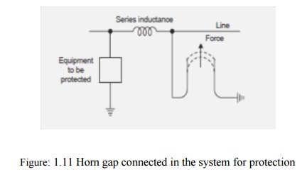
Whenever a surge voltage exceeds the breakdown value of the gap a discharge takes place and the energy content in the rest part of the wave is by-passed to the ground. An arc is set up between the gap, which acts like a flexible conductor and rises upwards under the influence of the electro-magnetic forces, thus increasing the length of the arc which eventually blows out. There are two major drawbacks of the horn gap; (i) The time of operation of the gap is quite large as compared to the modern protective gear. (ii) If used on isolated neutral the horn gap may constitute a vicious kind of arcing ground. For these reasons, the horn gap has almost vanished from important power lines.
Surge Diverters
The following are the basic requirements of a surge diverter:
· It should not pass any current at normal or abnormal (normally 5% more than the normal voltage) power frequency voltage.
· It should breakdown as quickly as possible after the abnormal high frequency voltage arrives.
· It should not only protect the equipment for which it is used but should discharge the surge current without damaging itself.
· It should interrupt the power frequency follow current after the surge is discharged to ground.
There are mainly three types of surge diverters: (i) Rod gap, (ii) Protector tube or expulsion type of lightning arrester, (iii) Valve type of lightning arrester. Rod gap This type of surge diverter is perhaps the simplest, cheapest and most rugged one. Fig. 1.12 shows one such gap for a breaker bushing. This may take the form of arcing ring. Fig. 1.13 shows the breakdown characteristics (volt-time) of a rod gap.
For a given gap and wave shape of the voltage, the time for breakdown varies approximately inversely with the applied voltage.

The time to flashover for positive polarity is lower than for negative polarities. Also it is found that the flashover voltage depends to some extent on the length of the lower (grounded) rod. For low values of this length there is a reasonable difference between positive (lower value) and negative flashover voltages. Usually a length of 1.5 to 2.0 times the gap spacing is good enough to reduce this difference to a reasonable amount. The gap setting normally chosen is such that its breakdown voltage is not less than 30% below the voltage withstand level of the equipment to be protected. Even though rod gap is the cheapest form of protection, it suffers from the major disadvantage that it does not satisfy one of the basic requirements of a lightning arrester listed at no. (iv) i.e., it does not interrupt the power frequency follow current. This means that every operation of the rod gap results in a L-G fault and the breakers must operate to de-energize the circuit to clear the flashover. The rod gap, therefore, is generally used as back up protection.
Expulsion type of lightning arrester
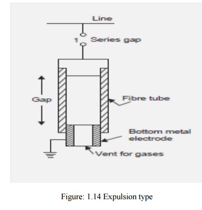
An improvement of the rod gap is the expulsion tube which consists of (i) a series gap (1) external to the tube which is good enough to withstand normal system voltage, thereby there is no possibility of corona or leakage current across the tube; (ii) a tube which has a fiber lining on the inner side which is a highly gas evolving material; (iii) a spark gap (2) in the tube; and (iv) an open vent at the lower end for the gases to be expelled (Fig. 1.14). It is desired that the breakdown voltage of a tube must be lower than that of the insulation for which it is used. When
3. Surge Protection of Rotating Machine
A rotating machine is less exposed to lightning surge as compared to transformers. Because of the limited space available, the insulation on the windings of rotating machines is kept to a minimum. The main difference between the winding of rotating machine and transformer is that in case of rotating machines the turns are fewer but longer and are deeply buried in the stator slots. Surge impedance of rotating machines in approx. 1000 Ω and since the inductance and capacitance of the windings are large as compared to the overhead lines the velocity of propagation is lower than on the lines. For atypical machine it is 15 to 20 metres/ μ sec. This means that in case of surges with steep fronts, the voltage will be distributed or concentrated at the first few turns. Since the insulation is not immersed in oil, its impulse ratio is approx. unity whereas that of the transformer is more than 2.0.
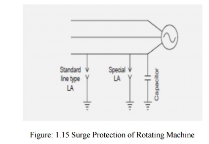
The rotating machine should be protected against major and minor insulations. By major insulation is meant the insulation between winding and the frame and minor insulation means inter-turn insulation. The major insulation is normally determined by the expected line-to-ground voltage across the terminal of the machine whereas the minor insulation is determined by the rate of rise of the voltage. Therefore, in order to protect the rotating machine against surges requires limiting the surge voltage magnitude at the machine terminals and sloping the wave front of the incoming surge. To protect the major insulation a special lightning arrester is connected at the terminal of the machine and to protect the minor insulation a condenser of suitable rating is connected at the terminals of the machine as shown in Fig. 1.15.
Related Topics