Chapter: Communication Theory : Angle Modulation
Narrow Band FM Modulation
NARROW BAND FM MODULATION:
The case where |θm(t)| << 1
for all t is called narrow band FM. Using the approximations cos x ~= 1 and sin
x ~= x for |x| << 1, the FM signal can be approximated as:
s(t) = Ac cos[ωct + θm(t)]
= Ac cos ωct cos θm(t) − Ac sin
ωctsin θm(t)
~= Ac cos ωct − Acθm(t) sin ωct
or in complex notation
s(t) = ACRE{ejwct (1 +
jθm(t) }
This is similar to the AM signal
except that the discrete carrier component Ac coswc(t) is 90° out of phase with
the sinusoid Ac sinwc(t) multiplying the phase angle θm(t). The spectrum of
narrow band FM is similar to that of AM.
ü The Bandwidth of an FM Signal:
The following formula, known as
Carson‘s rule is often used as an estimate of the FM signal bandwidth: BT =
2(∆f + fm) Hz
where ∆f is the peak frequency
deviation and fm is the maximum baseband message frequency component.
ü FM Demodulation by a Frequency
Discriminator:
A frequency discriminator is a
device that converts a received FM signal into a voltage that is proportional
to the instantaneous frequency of its input without using a local oscillator
and, consequently, in a non coherent manner.
• When the instantaneous frequency
changes slowly relative to the time-constants of the filter, a quasi-static
analysis can be used.
• In quasi-static operation the
filter output has the same instantaneous frequency as the input but with an
envelope that varies
according to the
amplitude response of the
filter at the instantaneous
frequency.
• The amplitude variations are then
detected with an envelope detector like the ones used for AM demodulation.
ü An
FM Discriminator Using the Pre-Envelope:
When θm(t) is small and band-limited
so that cos θm(t) and sinθm(t) are essentially band-limited signals with cut
off frequencies less than fc, the pre-envelope of the FM signal is
s+(t) = s(t) + jˆs(t) = Acej(ωct+θm(t))
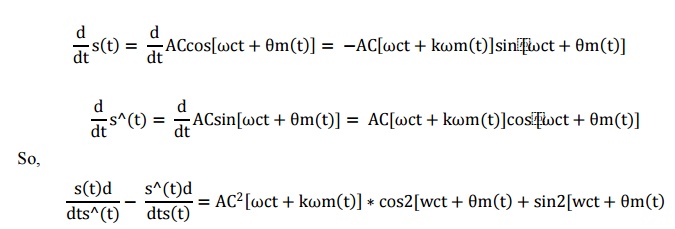
The angle of the pre-envelope is
φ'(t) = arctan[ˆs(t)/s(t)] = ωct + θm(t)
The derivative of the phase is =ωct+
kθm(t)

which is exactly the instantaneous
frequency. This can be approximated in discrete-time by using FIR filters to
form the derivatives and Hilbert transform. Notice that the denominator is the
squared envelope of the FM signal.
This formula can also be derived by
observing,
The
bandwidth of an FM discriminator must be at least as great as that of the
received FM signal which is usually much greater than that of the baseband
message. This limits the degree of noise reduction that can be achieved by
preceding the discriminator by a bandpass receive filter.
ü Using a Phase-Locked Loop for FM
Demodulation:
A device
called a phase-locked loop (PLL) can be used to demodulate an FM signal with
better performance in a noisy environment than a frequency discriminator. The
block diagram of a discrete-time version of a PLL as shown in figure,
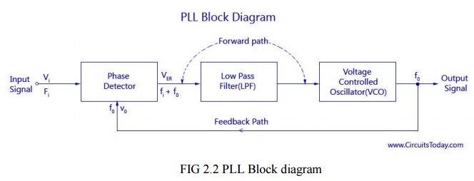
The block
diagram of a basic PLL is shown in the figure below. It is basically a flip
flop consisting of a phase detector, a low pass filter (LPF),and a Voltage
Controlled Oscillator (VCO) The input signal Vi with an input frequency fi is
passed through a phase detector. A phase detector
basically
a comparator which compares the input frequency fiwith the feedback frequency
fo .The phase detector provides an output error voltage Ver (=fi+fo),which is a
DC voltage. This DC voltage is then passed on to an LPF. The LPF removes the
high frequency noise and produces a steady DC level, Vf (=Fi-Fo). Vf also
represents the dynamic characteristics of the PLL.
The DC
level is then passed on to a VCO. The output frequency of the VCO (fo) is
directly proportional to the input signal. Both the input frequency and output
frequency are compared and adjusted through feedback loops until the output
frequency equals the input frequency. Thus the
PLL works
in these stages – free-running, capture and phase lock.
As the
name suggests, the free running stage refer to the stage when there is no input
voltage applied. As soon as the input frequency is applied the VCO starts to
change and begin producing an output frequency for comparison this stage is
called the capture stage. The frequency comparison stops as soon as the output
frequency is adjusted to become equal to the input frequency. This stage is
called the phase locked state.
ü Comments on PLL Performance:
• The
frequency response of the linearized loop characteristics of a band-limited
differentiator.
• The
loop parameters must be chosen to provide a loop bandwidth that passes the
desired aseband message signal but is as small as possible to suppress
out-of-band noise.
• The PLL
performs better than a frequency discriminator when the FM signal is corrupted
by additive noise. The reason is that the bandwidth of the frequency
discriminator must be large enough to pass the modulated FM signal while the
PLL bandwidth only has to be large enough to pass the baseband message. With
wideband FM, the bandwidth of the modulated signal can be significantly larger
than that of the baseband message.
ü Bandwidth of FM PLL vs. Costas Loop:
The PLL
described in this experiment is very similar to the Costas loop presented in
coherent demodulation of DSBSC-AM. However, the bandwidth of the PLL used for
FM demodulation must be large enough to pass the baseband message signal, while
the Costas loop is used to generate a stable carrier reference signal so its
bandwidth should be very small and just wide enough to track carrier drift and
allow a reasonable acquisition time.
Related Topics