Chapter: Linear Integrated Circuits : Analog Multiplier and PLL
Monolithic Phase Locked Loops (PLL IC 565)
Monolithic
Phase Locked Loops (PLL IC 565):
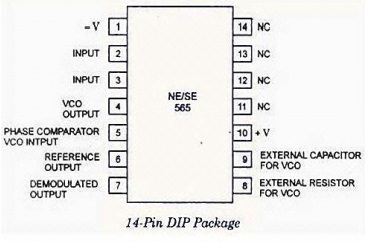
Pin Configuration of PLL IC 565
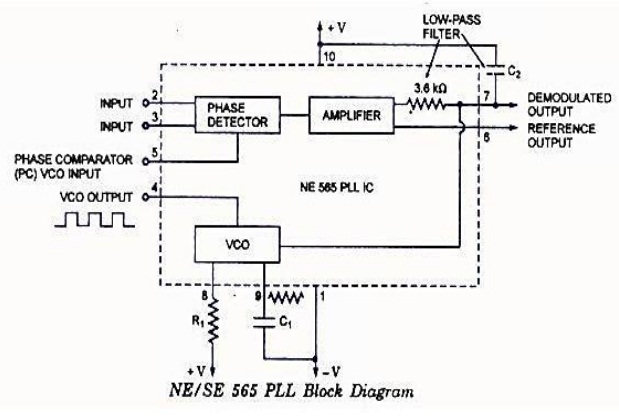
Basic Block Diagram Representation of IC 565
The
important electrical characteristics of the 565 PLL are,
·
Operating
frequency range: 0.001Hz to 500 Khz.
·
Operating
voltage range: ±6 to ±12v
·
Input
level required for tracking: 10mv rms min to 3 Vpp max
·
Input
impedance: 10 K ohms typically.
·
Output
sink current: 1mA
·
Output
source current: 10 Ma
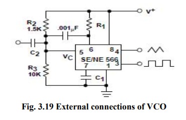
The
center frequency of the PLL is determined by the free running frequency of the
VCO, which is given by
fOUT = 1.2/ 4R1C1
where
R1&C1 are an external resistor & a capacitor
connected to pins 8 & 9.
·
The
VCO free-running frequency fOUT is adjusted externally with R1 & C1 to be
at the center of the input frequency range.
·
C1
can be any value; R1 must have a value between 2 k ohms and 20 K
ohms.
·
Capacitor
C2 connected between 7 & +V.
·
The
filter capacitor C2 should be large enough to eliminate variations
in the demodulated output voltage in order to stabilize the VCO frequency.
The
lock range fL & capture range fc of PLL is given by,
∆fL=
±7.8 fout/ V Hz
Where
fOUT = free running frequency of VCO (Hz)
V
= (+Vcc)-(-Vcc) volts
∆fC=
±[ ∆fL/(2Π)(3.6)(103)C2 ]½
Related Topics