Chapter: Physics : Magnetic Materials
Magnetic Materials
Magnetic Materials
1
Introduction
1.1
Basic Definitions
2
Origin of Magnetic Moments
3
Classification of Magnetic Materials
3.1
Diamagnetic materials
3.2
Paramagnetic Materials
3.3
Ferromagnetic materials
3.4
Dia, Para and Ferro magnetic materials – Comparison
4
Domain Theory of Ferromagnetism
4.1
Energies involved in the domain growth (or) Origin of Domain theory of
Ferromagnetism
5
Antiferromagnetic Materials
6
Ferrimagnetic Materials
7
Hysteresis
7.1
Explanation of hysteresis on the basis of Domains
8
Hard and Soft Magentic Material
8.1
Hard Magnetic Materials
8.2
Soft Magnetic Materials
8.3
Difference between Hard and Soft magnetic materials
9
Ferrites
9.1
Properties
9.2
Structures of Ferrites
9.3
Regular spinal
9.4
Inverse spinal
9.5
Types of interaction present in the ferrites
9.6
Properties of ferromagnetic materials
9.7
Application of Ferrites
10
Magnetic Recording and Readout Memory
10.1
Magnetic parameters for Recording
10.2
Storage of Magnetic Data
10.3
Magnetic Tape
10.4
Magnetic Disc Drivers
10.5
Floppy Disk
10.6
Magnetic bubble Materials
1 INTRODUCTION
The
materials which can be made to behave like a magnet and which are easily
magnetic field called as a magnetic materials.
1.1 Basic Definitions
1. Magnetic Dipole Moment (M)
The
dipole moment is defined as the product of magnetic pole strength and length of
the magnet. It is given by M = ml. Amp m2.
2. Magnetic Field
The space
around which the magnetic lines of forces exist is called as magnetic field.
Magnetic field is produced by permanent magnets such as a horse shoe magnet and
temporarily by elelctromagnets (or) superconducting magnets.
3. Magnetic Lines of Force
The
continuous curve in a magnetic field that exists from north pole to south pole
is called as magnetic lines of force.
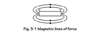
Fig. 3.1
Magnetic lines of force
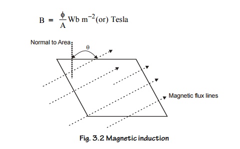
4. Magnetic Induction (B) (or) Magnetic Flux
Density
It is the
number of magnetic lines of force passing through unit area of cross section.
5. Magnetic Field Strength (or) Magnetizing Field
(H)
It is the
force experienced by a unit north pole placed at a given point in a magnetic
field. The magnetic induction B due to the magnetic field of intensity H
applied
in vacuum is related by B =μ 0H Amp m–1.
6. Magnetic Flux (ϕ )
The total
number of magnetic lines of force passing through a surface.
Unit : Weber.
7. Intensity of Magnetization (I)
Magnetization
is the process of converting a non-magnetic material in to a magnetic material.
It is
also defined as the magnetic moment per unit volume. I = m / V web m–2.
8. Magnetic Permeability (μ )
It is ratio of the magnetic induction (B) to the applied magnetic field intensity (H). μ= B / H
Unit: Henry m–1
It is the
measure of ability of the material to permit magnetic lines of force.
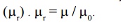
9. Relative Permeability ( μr)
It is
defined as the ratio of permeability of the medium to the permeability of the
free space
10. Magnetic Susceptibility χ
It is defined as the ratio of intensity of magnetization (I) and intensity of magnetic field (H). χ= I / H.
The sign and magnitude of χ are used to
determine the nature of the magnetic materials.
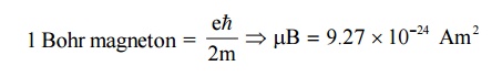
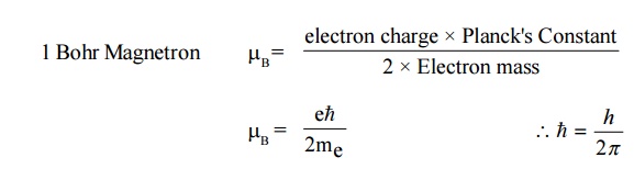
11. Bohr Magnetron ( μB)
The
orbital magnetic moment and the spin magnetic moment of an electron in an atom
can be expressed in terms of atomic unit of magnetic moment called as Bohr
magnetron.
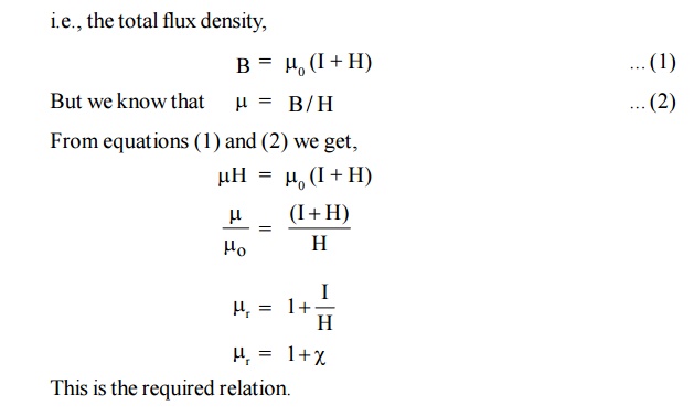
12. Relation between susceptibility (χ ) and Relative permeability ( μr)
We know
that when a current is supplied through a coil, magnetic field is developed.
When a magnetic material is placed inside a external magnetic field, the
magnetic flux density (B) arises due to applied magnetic field (H) and also due
to the induced magnetization (I).
i.e., the
total flux density,
13. Retentivity or Remanence
When an
external field is applied to the specimen it is magnetized and when the field
is removed it is demagnetized. But some materials do not completely demagnetize
when field is removed. There is some magnetism left out in the specimen. “This
residual magnetism which is left out even after the removal of the external
magnetic field” is called as the Retentivity or Remanence.
14. Coercivity
The
residual magnetism can be removed completely from the material by applying a
reverse magnetic field. “The reverse magnetic field which is used to completely
remove the residual magnetism” is called as the coercivity.
2 ORIGIN OF MAGNETIC MOMENTS
The
macroscopic magnetic properties of a substance are a consequence of magnetic
moments associated with individual electrons. Each electron in an atom has
magnetic moments that originate from the following two sources
Orbital magnetic moment of electrons
Spin magnetic moment of electrons.
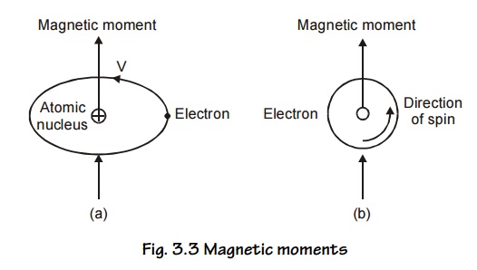
Magnetic
moments associated with an orbiting electron and a spinning electron is shown
in Fig.3.3 (a and b).
We know
that the electrons in an atom revolve around the nucleus in different orbits.
Basically, there are three contributions for the magnetic dipole moment of an
atom.
The
orbital motion of electrons (the motion of electrons in the closed orbits
around the nucleus). It is called as orbital magnetic moment. Its magnitude is
always small. Spin motion of the electrons (i.e. due to electron spin angular
momentum) and it is called as spin magnetic moment.
The
contribution from the nuclear spin (i.e., due to nuclear spin angular
momentum). Since this is nearly 103 times smaller than that of
electron spin, it is not taken into consideration.
For all
practical purposes, we assume that the magnetic moment arises due to the
electron spin ignoring the orbital magnetic moments and the nuclear magnetic
moments as their magnitudes are small.
We may
note that permanent magnetic moments can also arise from spin magnetic moments
of the nucleus. Of all the three, the spin dipole moments of electrons are
important in most magnetic materials.
1. Orbital angular momentum
This
corresponds to permanent magnetic dipole moments. Let us consider an electron
describing a circular orbit of radius ‘r’ with a stationary nucleus at the
centre as shown in Fig 3.3.(a). Let the electron rotate with a constant angular
velocity of ‘w’ radians per second.
Electron
revolving in any orbit may be considered as current carrying circular coil
producing magnetic field perpendicular to its plane. Thus the electronic orbits
are associated with a magnetic moment. The orbital magnetic moment of an
electron in an atom can be expressed in terms of atomic unit of magnetic moment
called Bohr Magnetron, defined as
2. Electron spin magnetic moment
The
concept of the electron having an angular momentum has been introduced in order
to explain the details of atomic spectra. This angular momentum of the electron
is referred to as the spin of the electron. Since the e- has a
charge, its spin produces a magnetic dipole moment.
According
to quantum theory, the spin angular momentum along a given direction is
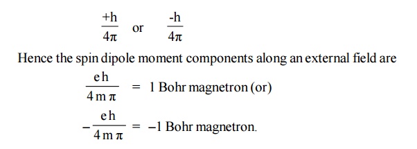
In a many
electron atom, the individual spin magnetic moments are added in accordance
with certain rules. Completely filled shells contribute nothing to the
resultant spin moment.
3. Nuclear magnetic moment
The
angular momentum associated with the nuclear spin is also measured in units of
h/2π . The mass of the nucleus is larger than that of an e- by the
order of 103. Hence nuclear spin magnetic moment is of the order of
10–3 Bohr magnetrons.
3 CLASSIFICATION OF MAGNETIC MATERIALS
The
magnetic materials are classified into two categories:
The materials without permanent magnetic moment Example:
1. Diamagnetic materials.
The materials with permanent magnetic moment. Example:
1. Paramagnetic materials
Ferromagnetic materials
Anti-Ferromagnetic materials
Ferrimagnetic materials.
3.1 Diamagnetic materials
Definition
In a
diamagnetic material the electron orbits are randomly oriented and the orbital
magnetic moments get cancelled. Similarly, all the spin moments are paired
i.e., having even number of electrons. Therefore, the electrons are spinning in
two opposite directions and hence the net magnetic moment is zero.
Effect of magnetic field
When an
external magnetic field is applied, the electrons re-orient and align
perpendicular to the applied field, i.e., their magnetic moment opposes the
external magnetic field.
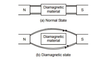
Fig.
3.4 Effect of magnetic field in Diamagnetic material
In the
above diagram, there is no penetration of magnetic lines through the
diamagnetic material.
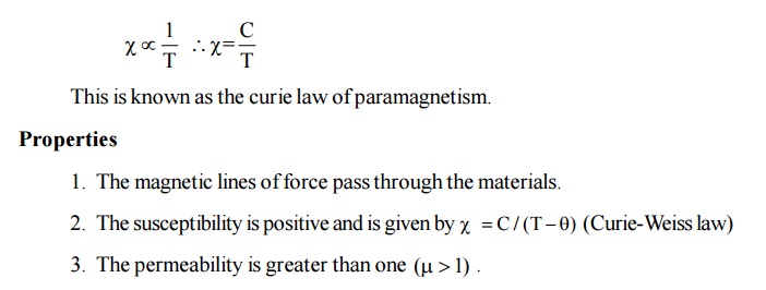
Properties
They repel the magnetic lines of force, if placed
in a magnetic field as shown in figure (3.4).
The susceptibility is negative and it is
independent to temperature and applied field strength. (X = –ve)
The permeability is less than one
There is no permanent dipole moment.
When the temperature is greater than the critical
temperature diamagnetic becomes normal material.
It has superconducting property.
Examples
: Gold, germanium, silicon, antimony, bismuth, silver, lead, copper, hydrogen,
Water and alcohol.
3.2 Paramagnetic
Materials
Definition
Para magnetism
is due to the presence of few unpaired electrons which gives rise to the spin
magnetic moment. In the absence of external magnetic field, the magnetic
moments (dipoles) are randomly oriented and possess very less magnetization in
it.
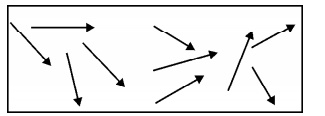
Fig.3.5
Paramagnetic Material
Effect of magnetic field
When an
external magnetic field is applied to paramagnetic material, the magnetic
moments align themselves along the field direction and the material is said to
be magnetized. This effect is known as paramagnetism.
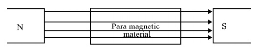
Fig.
3.6 Effect of magnetic field in paramagnetic material
Thermal
agitation disturbs the alignment of the magnetic moments with an increase in
temperature, the increase in thermal agitation tends to randomize the dipole
direction thus leading to decrease in magnetization.
This
implies that the paramagnetic susceptibility decreases with increase in
temperature. It is observed that the paramagnetic susceptibility varies
inversely with temperature.
There is a permanent magnetic moment.
When the temperature is less than the Curie
temperature, paramagnetic materials become diamagnetic materials.
It spin alignment is random in nature.
Examples
: Platinum, CuSO 4 , MnSO4 , Aluminum, etc
3.3 Ferromagnetic materials
Definition
Ferromagnetism
is due to the presence of more unpaired electrons. Even in the absence of
external field, the magnetic moments align parallel to each other. So that it
has large magnetism. This is called spontaneous magnetization.
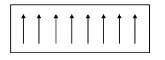
Fig. 3.7
Ferromagnetic materials
Effect of magnetic field
If a
small external magnetic field is applied the magnetic moments align in the
field direction and become very strong magnets.
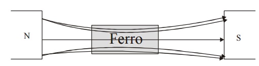
Fig.3.8
Effect of magnetic field in ferromagnetic material
Properties of ferromagnetic materials
1. All
the magnetic lines of force pass through the material.
The permeability is very much greater than one.
They have enormous permanent dipole moment.
When the temperature is greater than the Curie
temperature, the Ferromagnetic material becomes paramagnetic material.
The ferromagnetic material has equal magnitude
dipole lying parallel to each other.
Examples:
Nickel,
iron, Cobalt, Steel, etc.
(Curie
temperature - The temperature below which a material can acts as
ferromagnetic material and above which it can acts as paramagnetic material is
called Curie temperature.)
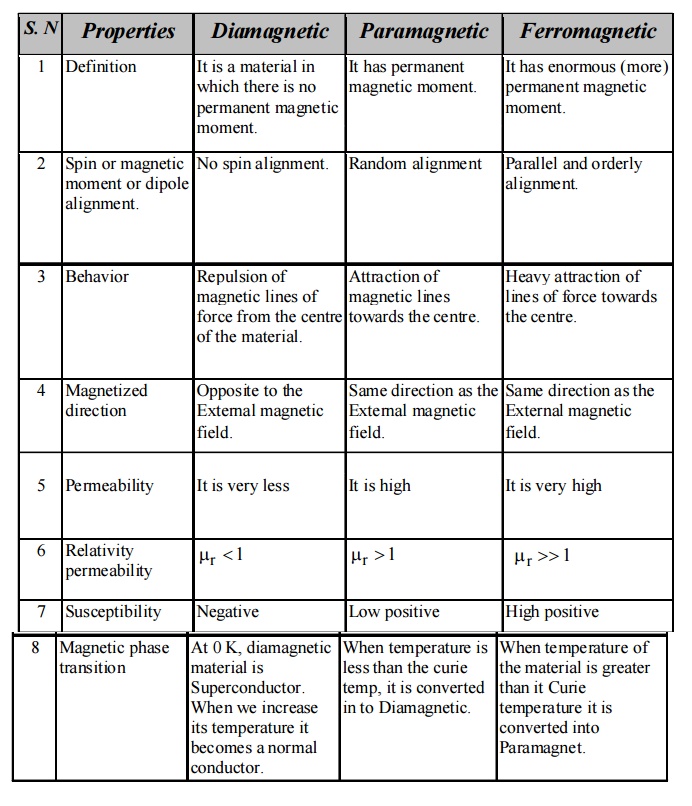
3.4 Dia, Para and Ferro magnetic materials –
Comparison
4 DOMAIN THEORY OF FERROMAGNETISM
This
theory was proposed by Weiss in 1907. It explains the hysteresis and the
properties of ferromagnetic materials.
Magnetic Domains
A
ferromagnetic material is divided into a large number of small region is called
domains. (0.1 to 1 of area), each direction is spontaneously magnetized. The
direction of magnetization varies from domain to domain and the net
magnetization is zero, in the absence external magnetic field. The boundary
line which separates two domains is called domain wall or Block wall. When the
magnetic field is applied to the Ferromagnetic material, the magnetization is
produced by two ways.
By the motion of domain walls.
By the rotation of domains.
Process of Domain magnetization
There are
two ways to align a random domain structure by applying an external magnetic
field.
1. By the motion of Domain walls
When a
small amount of magnetic field is applied, the domains having dipoles parallel
to the applied magnetic field increases in area by the motion of domain walls.
(Fig. 3.9 (2)).
2. By the rotation of Domains
If the
applied magnetic field is further increased, the domains are rotated parallel
to the field direction by the rotation of domains. (fig. 3.9 (3)).
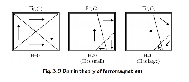
Fig. 3.9
Domin theory of ferromagnetism
Energies involved in the domain growth (or)
Origin of Domain theory of Ferromagnetism
We can
understand the origin of domains from the thermodynamic principle i.e., in
equilibrium, the total energy of the system is minimum.
The total
internal energy of the domain structure in a ferromagnetic material is made up
from the following contributions.
Exchange energy (or) Magnetic field energy.
Crystalline energy (or) Anisotropy energy.
Domain wall energy (or) Bloch wall energy.
Magnetostriction energy
Exchange
energy (or) Magnetic Field energy
“The
interaction energy which makes the adjacent dipoles align themselves” is the
called exchange energy (or) magnetic
field energy.
The
interaction energy makes the adjacent dipoles align themselves. It arises from
interaction of electron spins. It depends upon the inter atomic distance. This
exchange energy also called magnetic field energy is the energy required in
assembling the atomic magnets into a single domain and this work done is stored
as potential energy. The size of the domains for a particular domain structure
may be obtained from the principle of minimum energy. The volume of the domain
may very between say, say, 10–2 to 10–6 cm3.
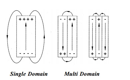
Fig. 3.10
Exchange energy in ferromagnetism
2. Anisotropy energy
The
excess energy required to magnetize a specimen in particular direction over
that required to magnetize it along the easy direction is called the crystalline anisotropy
energy.
In
ferromagnetic materials there are two types of directions of magnetization
namely,
Easy direction and
hard directions.
In easy
direction of magnetization, weak field can be applied and in hard direction of
magnetization, strong field should be applied.
Crystalline
anisotropy energy is energy of magnetization which is the function of
crystal orientation. As shown in figure magnetization curves for iron with the
applied field along different crystallographic direction crystallographic
directions have been drawn. For example, in BCC iron the easy direction is
[100], the medium direction is [110], and the hard direction [111]. The energy
difference between hard and easy direction to magnetize the material is about.
This energy is very important in determining the characteristic domain
boundaries.
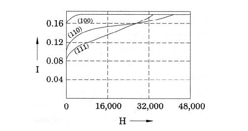
Fig.
3.11 Anisotropy energy in ferromagnetism
3. Domain wall energy or Bloch wall energy
A thin
boundary or region that separates adjacent domains magnetized in different
directions is called domain wall or Bloch wall.
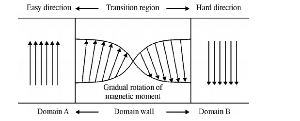
Fig.
3.12 The change of electron spin in the transition region of Bloch wall
The size
of the Bloch walls is about 200 to 300 lattice constant thickness. In going
from one domain to another domain, the electron spin changes gradually as shown
in figure. The energy of domain wall is due to both exchange energy and
anisotropic energy.
Based on
the spin alignments, two types of Bloch walls may arise, namely
Thick wall: When the spins at the boundary
are misaligned and if the direction of
the spin changes gradually as shown
figure, it leads to a thick Bloch wall. Here the misalignments of spins are
associated with exchange energy.
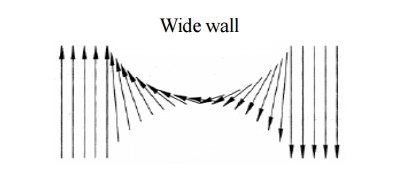
Fig.
3.13 The change of electron spin in the transition region of thick wall
Thin wall: When the spins at the boundaries changes abruptly, then the anisotropic energy becomes very less.
Since the anisotropic energy is directly proportional to the thickness of the
wall, this leads to a thin Bloch wall.
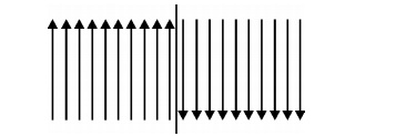
Fig.3.14
The change of electron spin in the transition region of thin wall
4. Magnetostriction energy
When a
material is magnetized, it is found that it suffers a change in dimensions.
This phenomenon is known as Magnetostriction.
This deformation is different along different crystal directions. So if the
domains are magnetized in different directions, they will either expand or
shrink. This means that work must be done against the elastic restoring forces.
The work done by the magnetic field against these elastic restoring forces is
called magneto-elastic energy or Magnetostrictive energy.
5 ANTIFERROMAGNETIC
MATERIALS
Definition
In this
material, the spins are aligned in anti-parallel manner due to unfavorable exchange
interaction among them, resulting in zero magnetic moment. Even when the
magnetic field is increased, it has almost zero induced magnetic moment.
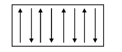
Fig.
3.15 Spin alignment of antiferromagnetic materials
Properties
1. It susceptibility
is very small and it is positive.
Examples
: Ferrous oxide, Fe Cl4 ,Mn O4 ,MnS
and some ionic compounds etc.
6 FERRIMAGNETIC MATERIALS
Definition
Ferrimagnetic
materials or Ferrites are much similar to Ferromagnetic materials. The magnetic
dipoles are aligned anti-parallel with unequal magnitudes. If small value of
magnetic field is applied, it will produce the large value of magnetization.
Ferrimagnetic
materials are widely used in high frequency applications and computer memories.
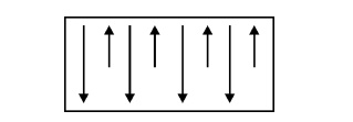
Fig.
3.16 Spin alignment of Ferrimagnetic materials
Properties
These materials have low eddy current loss and low
hysteresis losses.
Examples:
Ferrous
Ferrites and Nickel Ferrites
7 HYSTERESIS
Hysteresis
means “Lagging” i.e., The Lagging of intensity of magnetization (I) behind the
intensity of magnetic field (H).
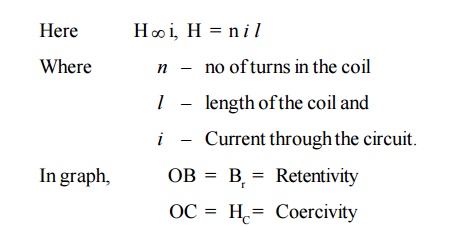
Experimental Determination
A graph
is drawn between the intensity of
magnetization [I] and the intensity
of magnetic field [H], for a cycle
of magnetization. The experimental setup consists of solenoid coil through which current is passed and the material
is magnetized. By varying the value of current we can get different values of
Intensity of magnetization [I] due to the magnetic field (H) in the solenoid.
When the
intensity of magnetic field ‘H’ is increased from O to F, the value of
Intensity of magnetization T if also increases from O to A, at ‘A’ the material
reaches the saturation value of Intensity of magnetization.
Then the
value of I is constant.
When intensity of magnetic field ‘H’ is decreased
from G to O, the value of Intensity of magnetization ‘I’ also decreases from A
to B, but not to zero (0). Now the material retains [stores] some amount of
magnetism known as Retentivity, even
though the intensity of magnetic field ‘H’ is zero. It is represented as ‘OB’ in the graph.
When intensity of magnetic field ‘H’ is increased
in reverse direction from O to C, the value of Intensity of magnetization ‘I’
decreases from B to C. i.e., the value of ‘I’ reaches zero.
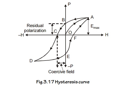
Fig.3.17
Hysteresis curve
The amount of intensity of magnetic field ‘H’
applied in the reverse direction to remove the retentivity is known as Coercivity
or Coercive force. It is represented as ‘OC’ in the graph.
Further repeating the process the remaining portion
[CDEFA] in the graph is obtained. The closed loop [OABCDEFA] is called
Hysteresis loop (or) (I – H) curve. For one cycle of magnetization.
Now the material is taken out. After a cycle of
magnetization, there is some expenditure (loss) of energy.
This loss of energy is radiated in the form of heat
energy in the material.
This loss of energy is directly proportional to the
area of the loop.
From the
Hysteresis graph, we can select soft and hard magnetic materials depending upon
the purpose.
Energy product
It is the
product of residual magnetism Br and coercivity which HC
gives the maximum amount of energy stored in the specimen.
Energy
product = Br × HC
Hysteresis loss
When the
specimen is taken through a cycle of magnetization. There is a loss of energy
in the form of heat. This loss of energy is known as Hysteresis loss.
7.1 Explanation of hysteresis on the basis of
Domains
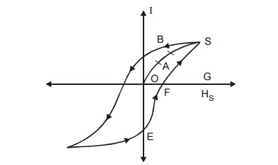
Fig.3.18
Hysteresis curve on the basis domain theory
OA - Due
to smaller reversible domains wall movement.
AB - Due
to larger irreversible domain wall movement.
BS - Due
to smaller irreversible domain rotation.
S -
Point of saturation.
When a
field is applied, for small H, the domain walls are displaced and gives rise to
small value of magnetization. [OA in the graph]. Now, the field is removed, the
domains return to its original state known as reversible domains.
When the
field is increases, a large number of domains contribute to the magnetization
and I increases rapidly with H.
Now, when
the field is removed the domain boundaries do not come back to the original
position due to the domain wall movement to a very large distance (AB in the
graph). These domains are called irreversible domains.
Now if
the field is further increased, domains start rotating along the field
direction and anisotropic energy is stored and it is represented as BC in the
graph.
Thus the
specimen is said to attain maximum magnetization at this position even after
the removal of the field. The material is having magnetism called Retentivity.
This Retentivity can be destroyed by applying a high reverse magnetic field
called coercivity.
Thus the
reversible and irreversible domain wall movements give rise to hysteresis in
the Ferromagnetic materials.
8 HARD AND
SOFT MAGENTIC MATERIAL
In
Hysteresis, after a cycle of magnetization, there is some expenditure (loss) of
energy. This loss of energy is radiated in the form of heat energy in the
material and it is directly proportional to the area of the loop. From the
Hysteresis graph, we can select the soft and hard magnetic materials.
8.1 Hard Magnetic Materials
The materials which are very difficult to magnetize
and demagnetize are called hard magnetic materials. These
materials can be made by heating the magnetic
materials and then cooling it suddenly.
It can also be prepared by adding impurities.
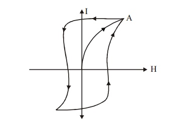
Fig.3.19
Hysteresis loop of a hard magnetic material
The above
hysteresis loop is very hard and has a large loop area for a hard magnetic
material, therefore the loss is also large. Domain wall does not move easily
and require large value of H for magnetization. Its coercivity and retentivity
values are large. Its eddy current loss is also high due to its low
resistivity, the magnetostatic energy is large. It has low susceptibility and
permeability. The hard magnetic materials have large amount of impurities and
lattice defects.
Examples
: Tungsten steel, Carbon steel,
Chromium steel, Alnico etc.,
Properties
It is easilly magnetised and demagnetised.
They hysteresis area is very small and hence, the
hysteresis loss is also small, as shown in figure.
The coercivity and rentenivity are very small.
These materials have large values of susceptibility
and permeabilty.
Their magnetostatic energy is very small.
The eddy current loss is very small.
Applications
Iron-Silicon alloys are used in electrical
equipment and magnetic cores of transformes.
Cast iron is used in the structure of electical
machinery and the frame work of D.C machine.
Nickel alloys are used to manufacture inductors,
relays and small motors.
It is also used for computer and data storage
devices.
8.2 Soft Magnetic Materials
The materials which are easily magnetized and
demagnetized are called soft magnetic materials. These
materials can be made by heating the
magnetic materials and then cooling
it slowly to attain an ordered
structure of atoms.
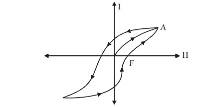
Fig.3.20
Hysteresis loop of a soft magnetic material
The above
hysteresis loop is very small and has a less loop area for a soft magnetic
materials. Therefore the loss is also small. Domain wall move easily and
require small value of H for magnetization. Its coercivity and retentivity
values are small, its eddy current loss is small due to its high resistivity.
The magnetostatic energy is less, it has high value of susceptibility and
permeability. The soft magnetic materials do not have impurities and lattice
defects.
Examples:
Iron-Silicon alloys, Nickel-Iron
alloys and Iron-cobalt alloys.
Properties
It is very hard to magnetize and also demagnetize.
The hysteresis cure is very broad and has a large
as shown in figure.
The coercivity and retentivity values are large.
These materials have low value of susceptibility
and permeability.
The magnetostatic energy is large.
The eddy current loss is very high.
Applications
Magnets made by carbon steel are used for
manufacturing the toys and compass needle.
Tungsten steel is used in making permanent magnets
for D.C motors.
It is also used for making a small size of magnets.
8.3 Difference between Hard and Soft magnetic
materials
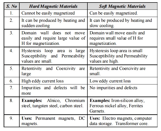
Hard Magnetic Materials
1. Cannot
be easily magnetized
2. It can
be produced by heating and sudden cooling
3. Domain
wall does not move easily and require large value of H for magnetization.
4.
Hysteresis loop area is large Susceptibility and Permeability values are small.
5.
Retentivity and Coercivity are large
6. High
eddy current loss
7.
Impurities and defects will be more
8.
Examples: Alnico, Chromium steel, tungsten steel, carbon steel.
9. Uses:
Permanent magnets, DC magnets.
Soft Magnetic Materials
1. Can be
easily magnetized.
2. It can
be produced by heating and slow cooling.
3. Domain
wall move easily and requires small value of H for magnetization.
4.
Hysteresis loop area is small Susceptibility and Permeability values are high.
5.
Retentivity and Coercivity are small.
6. Low
eddy current loss
7. No
impurities and defects
8.
Examples: Iron-silicon alloy, Ferrous nickel alloy, Ferrites Garnets.
9. Uses:
Electro magnets, computer data storage. Transformer core.
9 FERRITES
Definition
Ferrites
or Ferrimagnetic materials are the modified structure of iron without carbon.
In Ferities the spins of adjacent ion is the presence of a magnetic field are
in opposite directions with different magnitudes.
9.1 Properties
These are made from ceramic ferromagnetic compounds.
It has low tensile strength and it is brittle and
soft.
In these materials all valence electrons are tied
up by ionic bonding.
These are bad conductors with high resistivity of
the order of 1011 m
Ferrites have low eddy current loss and low hysteresis
loss.
The general formula for Ferrites is X²+
(Fe2)3+ O4 where X-may is a metal (divalent
metal) such as Mg, Ni, Mn, Zn, etc.
Ferrites are manufactured by powder metallurgical
process by mixing, compacting and then sintering at high temperatures followed
by age hardening in magnetic fields.
9.2 Structures
of Ferrites
Ferrites
are the magnetic compounds consisting to two or more different kinds of atoms.
Generally ferrites are expressed as X²+ (Fe2)3+ O 4 where
X²+ stands for suitable divalent metals ions such etc Mg2+,
Zn2+, Fe2+, Mn2+, Ni2+ etc.
Normally,
there are two types of structures present in the ferrites
1.
Regular spinel 2. Inverse spinel
9.3
Regular spinal
In the
regular spinal type, each metal atom (divalent) is surrounded by fourions in a
tetragonal fashion.
For
example in Mg2+, Fe23+, O42+,
the structure of Mg2+is given in the Fig. 3.21 and it is called “A’
site. Totally in a unit cell, there will be 8 tetrahedral (8A) sites.
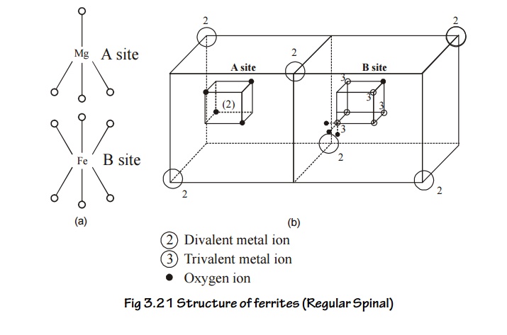
Each Fe3+
(trivalent) is surrounded by ‘6’ O2 ions and forms an
octahedral fashion as show in Fig.3.20. Totally there will be 16 such
octahedral sites in the unit cell. This in indicated by ‘B’ site.
Thus in a
regular spinal, each divalent metal ion (mg2+) exists in a
tetrahedral form (A site) and each trivalent metal ion (Fe2+) exists
in an octahedral form (B site). Hence, the sites A and B combine together to
form a regular spinal ferrite structure as shown in Fig.3.21.
9.4
Inverse spinal
In this
type, we consider the arrangement of dipoles of a single ferrous ferrite
molecule Fe3+ [Fe2+ Fe3+] O42–
Fe3+ , ions (trivalent) occupies all A sites (tetrahedral) and half
of the B sites (octahedral) also.
Thus the
left out B sites will be occupied by the divalent (Fe2+). The
inverse spinal structure is shown in the Fig. 3.22.
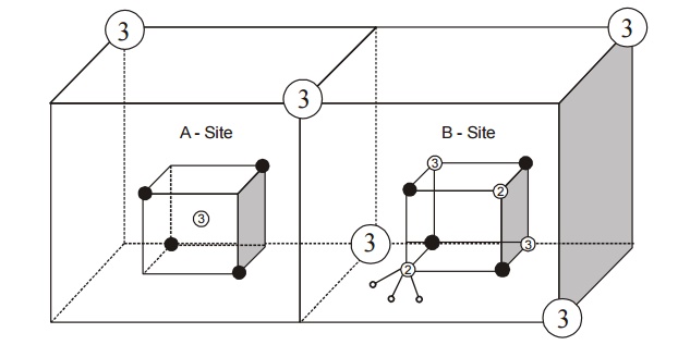
Fig.3.22
Structure of ferrites (inverse Spinal)
9.5 Types of interaction present in the ferrites
The spin
arrangement between the A site B site is in an ant parallel manner and it was
explained by Neel. According to him, in ferrites, the spin arrangement is ant
parallel and there exists some interaction between the A and B sites which is
represented as AB interaction.
Apart
from this, there are two more interactions (i.e.,) AA and BB interaction which
is negative and considerable weaker than AB interaction.
The
tendency of AB interaction is to align all A spins parallel to each other and
anti parallel to all B spins, but the tendency of AA and BB interaction is to
spoil the parallel arrangement of AB spins respectively.
Since AB
is very strong as compared with AA and BB, the effect of AB interaction
dominates and gives rise to anti parallel spin arrangement.
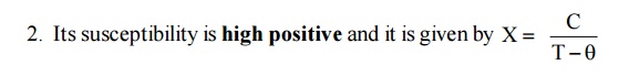
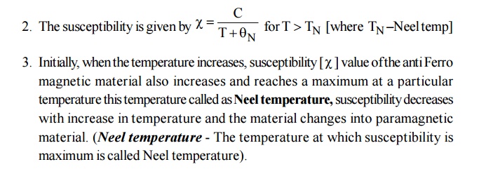
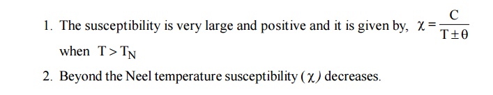
9.6 Properties
of ferromagnetic materials
Ferromagnetic materials posses’ net magnetic
moment.
Above Curie temperature, it becomes paramagnetic
while it behaves as ferromagnetic material below Curie temperature.
The susceptibility of Ferrimagnetic material is
very large and positive. It is temperature dependent and is given by
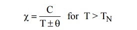
Beyond Neel temperature,decreases.
Spin alignment is anti parallel of different
magnitudes.
Mechanically, it has pure ion character.
They have high permeability and high resistivity.
They have low eddy current losses and low
hysteresis.
9.7 Application
of Ferrites
Ferrites are used to produce ultrasonic wave by
Magnetostriction principle.
Ferrites are used in audio and video transformers.
Ferrites rods are used in radio receivers to
increase the sensitivity.
Ferrites
are widely used in non-reciprocal microwave devices such as gyrator, circulator
and Isolator.
Gyrator : It transmits the power freely in both
directions with a phase shift of radians.
Circulator : It
provides sequential transmission of power between the ports.
Isolator : It is used to display differential
attenuation.
They are also used for power limiting and harmonic
generation.
Ferrites are used in parametric amplifiers so that
the input can be amplified with low noise.
They are used in computers and data processing
circuits.
Bi-stable elements, Ferro cube (Ferrite with square
hysteresis loop), magnetic shift register, and magnetic bubbles are also
examples for Ferrites.
10 MAGNETIC
RECORDING AND READOUT MEMORY
Nowadays,
large number of information are stored in (or) retrieved from the storage
devices, by using devices is magnetic recording heads and they function
according to the principle of magnetic induction.
Generally
Ferro or Ferrimagnetic materials are used in the storage devices because in
this type of materials only the magnetic interaction between only two dipoles
align themselves parallel to each other.
Due to
this parallel alignment even if we apply small amount of magnetic field, a
large value of magnetization is produced. By using this property information
are stored in storage devices.
In the
storage devices, the recording of digital data (0’s and 1’s) depends upon the
direction of magnetization in the medium.
10.1
Magnetic parameters for Recording
When current is passed through a coil, a magnetic
field is induced. This principle called “Electromagnetic Induction” is used in
storage devices.
The case with which the material can be magnetized
is another parameter.
We know the soft magnetic materials are the
materials which can easily be magnetized and demagnetized. Hence a data can be
stored and erased easily. Such magnetic materials are used in temporary storage
devices.
Similarly, we know hard magnetic materials cannot
be easily magnetized and demagnetized. So such magnetic materials are used in
permanent storage devices.
In soft magnetic materials, the electrical
resistance varies with respect to the magnetization and this effect is called
magneto-resistance. This parameter is used in specific thin film systems.
The
magnetic medium is made of magnetic materials (Ferro or Ferric oxide) deposited
on this plastic.
The
magnetic medium move across the read / write heads and either logic 1’s and
logic 0’s are written on the medium. The magnetized spots on the medium
generate small electrical signals and this different direction signals
represents logic is and 0’s on the medium.
10.2
Storage of Magnetic Data
Memory
units are the devices used to store the information (Input and Output) in the
form of bits [8bits = 1 Byte].
The
memory units are classified into two categories.
Main memory (Primary) or Internal Memory.
Auxiliary Memory (Secondary) or External Memory.
Main
Memory
The
memory unit of the central processing unit (CPU) is called as main memory.
Compare a black beard main memory. We can write many data on memories and
finally erase it if we want.
Example :
RAM, ROM,
EPROM etc.
2. Auxiliary Memory
Since
storage capacity of primary memory is not sufficient secondary memory units are
developed to store the large volume of data. Separately and hence called as
extra (or) additional (or) external memory.
This type
of memory is also referred to as back up storages because, it is used to store
large volume of data on a permanent basis.
Example: 1.
Magnetic tapes
Magnetic
disk (Floppy and Hard disc)
Ferrite core memories
Magnetic bubble memories.
10.3 Magnetic
Tape
It is one
of the most popular storage medium for data. The tape is a plastic ribbon with
metal oxide material coated on one side which can be magnetized. In this,
information can be written and also can be read by read / write heads.
Information
recorded in the tape is in the form of tiny magnetized and non magnetized spots
on the metal oxide coating.
The
magnetized spot represents ‘I’ and un magnetized spot represent ‘0’ in binary
code. The information can be accessed, processed, erased and can be again
stored in the same area.
Advantages
Its storage capacity is large
It is easy to handle and is portable
Its cost is less than other storage devices.
It can be erased and reused may times.
Disadvantage
1. It
consumes lot of time.
10.4
Magnetic Disc Drivers
These
disks are direct access storage devices. These disks are magnetically coated.
There are two types of disks.
Hard disc
Floppy disc
Hard disc
The hard
disc is made of hard aluminum platters. The platter surface is carefully
machined until it is flat (or) plane. The platter surface is coated with
magnetic material (magnetic oxides). The platter is built into a box.
Similar
such disks are mounted on a vertical shaft, forming a disk pack and it is shown
in fig.
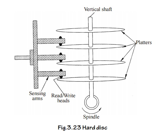
Fig.3.23
Hard disc
The disc
pack is placed is a drive mechanism called hard disk drive. The drive mechanism
driver the disc pack with the spindle. The data is written (or) ready by R/ W
beads in the horizontal sensing arms by moving in an out between the platters
with the precaution that the R/W head doesn’t touch the surface instead, it fly
over the disk surface by a fraction of an mm.
Advantages
It has very large storage capacity.
Thousands of files can be permanently stored
Very high speed is reading and writing the
information.
This is prevented from dust particles, since they
are seated in special chamber.
Disadvantages
It is very costly.
It data is once corrupted, there is a heavy loss of
data.
10.5
Floppy Disk
The hard
disc is suitable only for large and medium sized computers and often are too
expensive for small computers systems. Floppy disc are the latest development
in secondary storage devices.
It is
made up of a flexible plastic material and hence called as floppy disc. It is
also called as diskette. It acts both as an input and output device.
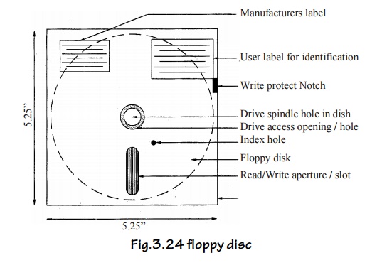
Fig.3.24 floppy disc
The disk is provided with a central hole. This
hole is used for mounting the disc in the floppy derive unit. The envelope
prevents the disk from dust and moisture.
There is a small index hole in the cover and
there will be a hole in the drive disk. When these two holes match then only
the storage operation can be started. Write protect notch is used to prevent
writing on the disc by other users. This can be done by covering the notch with
a sticker. A 5.25° floppy is shown in fig.
Writing
operation
When the floppy disk moves over the gap the CPU
flow through the write will of the head and magnetizes the iron oxide coating
in the disk to the proper pattern.
Reading
Operation
When the data are to be read, the magnetized
patterns induces pulses of current in the read coil and is amplified then fed
to the CPU. Thus data can be stored and accessed from the floppy disc on both
sides (or) single side. Reading / writing data on the magnetic medium using
frequently modulated wave.
Special features
The cost is very low
It can be easily handled
It can be taken to any place
It has high storage capacity
Many types of floppies are available, depending on
their storage capacities.
Disadvantage
Here the
magnetic disk is moved (rotated) mechanically.
10.6
Magnetic bubble Materials
Magnetic
bubble is direct access storage medium, magnetic bubbles are soft magnetic
materials with magnetic domains of a few micrometers in diameter. These bubbles
are the electrical analogue of the magnetic disk memories used in computers.
The
magnetic disk in the hard disk memory is moved mechanically where as the
bubbles in a bubble memory device are moved electronically at very high speeds,
so the read out time or storing time is greatly reduced in bubble memory
device. The bubble units are made with solid state electronic chips.
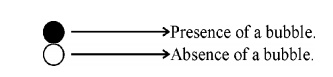
A
magnetic bubble can be thought of as a positively charged and in a negatively
charged magnetic film.The presence of a bubble is on ‘ON’ condition and the
absence of a bubble is an ‘off’ condition. ie., [1 or 0].
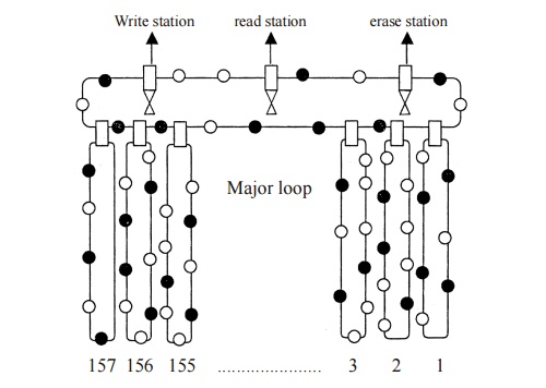
Fig. 3.25
Magnetic bubble memory
Figure
shows the schematic diagram of a magnetic bubble memory. It consists of one
major loop and 157 minor loops. Each minor loop has 641 bubble sites.
Writing operation
When a
data is to be stored, the bubbles from the minor loops are transferred to the
major loop, and it goes to the write station. In write station the data is
entered and the bubble again comes to minor loop.
Reading operation
To read
the data from the storage, the bubble from minor loops are transferred to the
major loop and it goes to the read station, then it comes to the minor loop.
The data can be altered by the erase station, if we need to erase it.
Advantage
It is non-volatile.
It has high storage capacity than the magnetic hard
disk.
It has high across speed.
Construction
A Bubble
memory consist of materials such as magnetic garnets and store the data as
microscopic magnets. A thin film of these garnets is deposited on a
non-magnetic substrate of Gadolinium Gallium Garnet in Integrated Circuit [IC]
form.
Related Topics