Chapter: Mechanical : Kinematics of Machinery : Gears and Trains
Gears and Trains
Gears And Trains
1 Introduction
Introduction: The slip and creep in the belt
or rope drives is a common phenomenon, in the transmission of motion or power between two shafts. The effect of
slip is to reduce the velocity ratio of the drive. In precision machine, in
which a definite velocity ratio is importance (as in watch mechanism, special
purpose machines..etc), the only positive drive is by means of gears or toothed
wheels.
Friction
Wheels: Kinematiclly, the motion and power transmitted by gears is equivalent
to that transmitted by friction wheels or discs in contact with sufficient
friction between them. In order to understand motion transmitted by two toothed
wheels, let us consider the two discs placed together.
When one
of the discs is rotated, the other disc will be rotate as long as the
tangential force exerted by the driving disc does not exceed the maximum
frictional resistance between the two discs. But when the tangential force
exceeds the frictional resistance, slipping will take place between the two
discs. Thus the friction drive is not positive a drive, beyond certain limit.
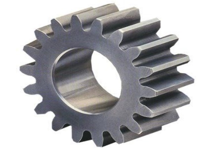
Gears are
machine elements that transmit motion by means of successively engaging teeth.
The gear teeth act like small levers. Gears are highly efficient (nearly 95%)
due to primarily rolling contact between the teeth, thus the motion transmitted
is considered as positive.
Gears
essentially allow positive engagement between teeth so high forces can be
transmitted while still undergoing essentially rolling contact. Gears do not
depend on friction and do best when friction is minimized.
Gears are
used to change speed in rotational movement.
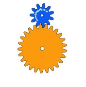
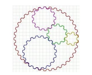
In the
example above the blue gear has eleven teeth and the orange gear has twenty
five. To turn the orange gear one full turn the blue gear must turn 25/11 or
2.2727r turns. Notice that as the blue gear turns clockwise the orange gear
turns anti-clockwise. In the above example the number of teeth on the orange
gear is not divisible by the number of teeth on the blue gear. This is
deliberate. If the orange gear had thirty three teeth then every three turns of
the blue gear the same teeth would mesh together which could cause excessive
wear. By using none divisible numbers the same teeth mesh only every seventeen
turns of the blue gear.
A gear or
cogwheel is a rotating machine part having cut teeth, or cogs, which mesh with
another toothed part to transmit torque. Geared devices can change the speed,
torque, and direction of a power source. Gears almost always produce a change
in torque, creating a mechanical advantage, through their gear ratio, and thus
may be considered a simple machine. The teeth on the two meshing gears all have
the same shape.[1] Two or more meshing gears, working in a sequence, are called
a gear train or a transmission. A gear can mesh with a linear toothed part,
called a rack, thereby producing translation instead of rotation.
The gears
in a transmission are analogous to the wheels in a crossed belt pulley system.
An advantage of gears is that the teeth of a gear prevent slippage.
When two
gears mesh, if one gear is bigger than the other, a mechanical advantage is
produced, with the rotational speeds, and the torques, of the two gears
differing in proportion to their diameters.
In
transmissions with multiple gear ratios—such as bicycles, motorcycles, and
cars—the term "gear" as in "first gear" refers to a gear
ratio rather than an actual physical gear. The term describes similar devices,
even when the gear ratio is continuous rather than discrete, or when the device
does not actually contain gears, as in a continuously variable transmission.
1.1 Fundamental Law of Gear-Tooth
Pitch point divides the line between the line of centers and its positiond ecides the velocity ratio of the two teeth. The above expression is the fundamental law of gear-tooth action.
Formation of teeth:
Involute
teeth
Cycloidal
teeth
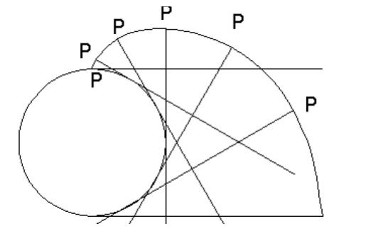
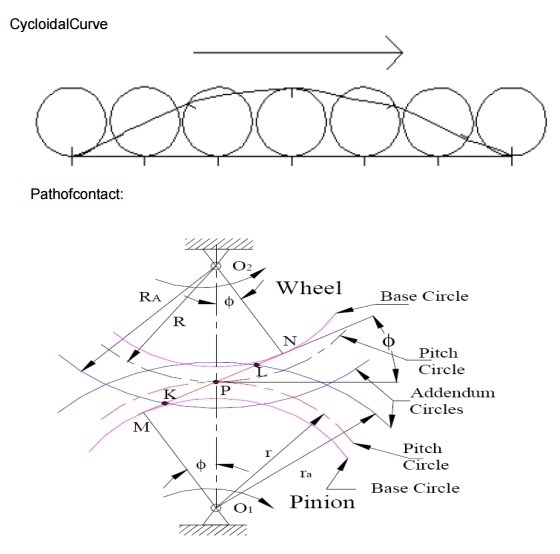
Involute curve:
The curve most commonly use d for gear-tooth
profiles is the involute of a circle. This involute
curve is the path traced by a point on a line as the line Rolls without
slipping on the circumference of a circle. It may also be defined
asapathtraced by the end of a string,
which is originally wrapped on a circle when the string is un wrapped from the
circle. The circle from which the involute is derived is called the base circle
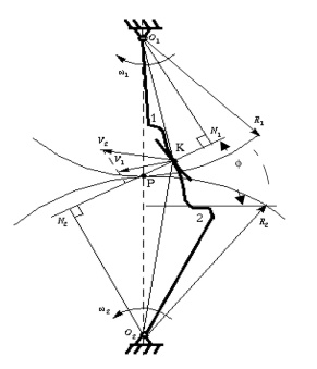
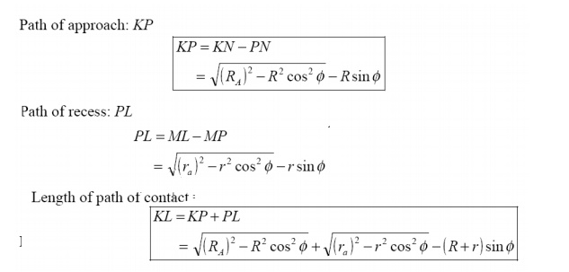
Consider a pinion driving wheel as shown in figure.
When the pinion rotates in clockwise, the contact between a pair of involute
teeth begin sat K(on the near the
base circle of pinion or the outer end of the tooth face on the wheel ) and end sat L (outer end of the tooth face on the pinion
or on the flank near the base circle of wheel).
MN is the
common normal at the point of contacts and the common tangent to the base circles. The point K is the intersection of the addendum circle of wheel and the
common tangent. The point L is the
intersection of the addendum circle of pinion and common tangent.
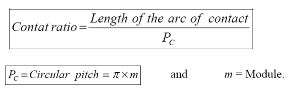
The
length of path of contact is the length of common normal cut-off by theaddendum
circles of the wheel and the pinion. Thus the length of part of contact is KL which is the sum of the
parts of path of contacts KP
and PL. Contact length KP is called as path of approach and contact length PL is called as path of
recess.
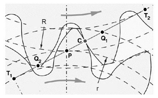
Arc of contact: Arc of
contact is the path traced by a point on the pitch circle from the beginning to the end of engagement of a given
pair of teeth. In Figure, the arc of contact is EPF or GPH.
The arc
GP is known as arc of approach and the arc PH is called arc of recess. The
angles subtended by these arcs at O1 are called angle of approach and angle of
recess respectively.

Contact Ratio ( or Number of
Pairs of Teeth in Contact)
The contact ratio or the number of pairs of teeth
in contact is defined as the ratio of the length of the arc of contact to the
circular pitch.
Continuous
motion transfer requires two pairs of
teeth in contact at the ends of the path
of contact, though the reisonly one pair in contact in the middle of the
path, as in Figure. The average
number of teeth in contact is an important parameter-If it is tool owdue the
use of inappropriate profile shift sortoan excessive centre distance. Them
anufacturinginaccuracies may lead to loss of kinematic continuity-that is to
impact, vibration and noise The average number of teeth in contact is also a
guide tolod sharing between teeth; it is termed the contact ratio.
The tooth
tip of the pinion will then undercut the tooth on the wheel at the root and
damages part of the involute profile. This effect is known as interference, and occurs when the teeth
are being cut and weakens the tooth at its root.
In
general, the phenomenon, when the tip of tooth undercuts the root on its mating
gear is known as interference.
Similarly,
if the radius of the addendum circles of the wheel increases beyond O2M,
then the tip of tooth on wheel will cause interference with the tooth on
pinion. The points M and N are called interference points.
Interference
may be avoided if the path of the contact does not extend beyond interference
points. The limiting value of the radius of the addendum circle of the pinion
is O1N and of the wheel is O2M.
The
interference may only be prevented, if the point of contact between the two
teeth is always on the involute profiles and if the addendum circles of the two
mating gears cut the common tangent to the base circles at the points of
tangency.
When
interference is just prevented, the maximum length of path of contact is MN.
Methods to avoid Interference
1.
Height of the teeth may be reduced.
2.Under cut
of the radial flank of the pinion.
3.Centre
distance may be increased. It leads to
increase in pressure angle.
4. By tooth
correction, the pressure angle, centre distance and base circles remain unchanged,
but tooth thickness of gear will be greater than the pinion tooth thickness.
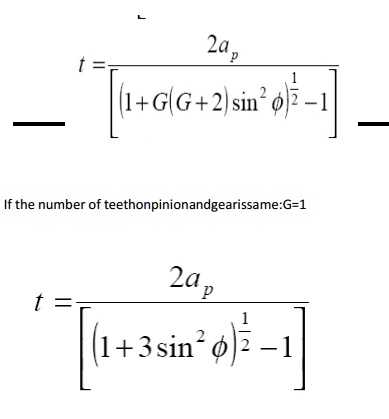
Minimum
number of teeth on the pinion avoid Interference
The
pinion turns clockwise and drives the gear as shown in Figure.
Points M
and N are called interference points. i.e., if the contact takes place beyond M
and N, interference will occur.
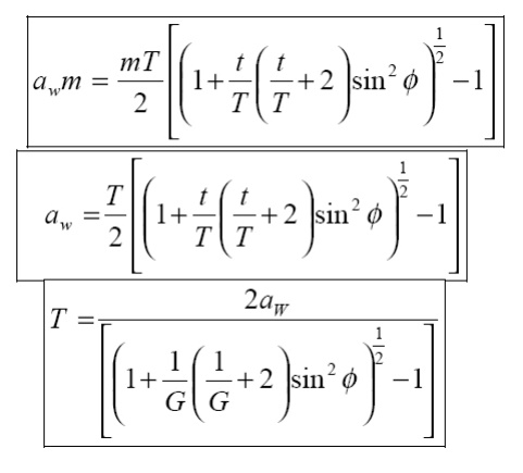
The
limiting value of addendum circle radius of pinion is O1N and the
limiting value of addendum circle radius of gear is O2M. Considering
the critical addendum circle radius of gear, the limiting number of teeth on
gear can be calculated.
Let
Ф = pressure angle
R = pitch
circle radius of gear = ½ mT
r = pitch
circle radius of pinion = ½ mt
T & t
= number of teeth on gear & pinion
m =
module
2 Spur Gear Terminology
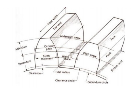
Addendum: The radial distance between the
Pitch Circle and the top of the teeth.
Arc of Action: Is the arc of the Pitch Circle
between the beginning and the end of the
engagement of a given pair of teeth.
Arc of Approach: Is the arc of the Pitch Circle
between the first point of contact of the gear teeth and the Pitch Point.
Arc of Recession: That arc
of the Pitch Circle between the Pitch Point and the last point of contact of the gear teeth.
Backlash: Play between mating teeth.
Base Circle: The circle from which is
generated the involute curve upon which the tooth profile is based.
Center Distance: The distance between centers of
two gears.
Chordal Addendum: The
distance between a chord, passing through the points where the Pitch Circle crosses the tooth profile, and
the tooth top.
Chordal Thickness: The
thickness of the tooth measured along a chord passing through the points where the Pitch Circle crosses
the tooth profile.
Circular Pitch: Millimeter of Pitch Circle circumference
per tooth.
Circular Thickness: The
thickness of the tooth measured along an arc following the Pitch Circle
Clearance: The distance between the top of a
tooth and the bottom of the space into which it fits on the meshing gear.
Contact Ratio: The ratio of the length of the
Arc of Action to the Circular Pitch.
Dedendum: The radial distance between the
bottom of the tooth to pitch circle.
Diametral Pitch: Teeth per mm of diameter.
Face: The working surface of a gear
tooth, located between the pitch diameter and the top of the tooth.
Face Width: The width of the tooth measured
parallel to the gear axis.
Flank: The working surface of a gear
tooth, located between the pitch diameter and the bottom of the teeth
Gear: The larger of two meshed gears.
If both gears are the same size, they are both called "gears".
Land: The top surface of the tooth.
Line of Action: That line along which the point
of contact between gear teeth travels, between the first point of contact and the last.
Module: Millimeter of Pitch Diameter to
Teeth.
Pinion: The smaller of two meshed gears.
Pitch Circle: The
circle, the radius of which is equal to the distance from the center of the
gear to the pitch point.
Diametral pitch: Teeth per millimeter of pitch
diameter.
Pitch Point: The point of tangency of the
pitch circles of two meshing gears, where the Line of Centers crosses the pitch circles.
Pressure Angle: Angle between the Line of Action
and a line perpendicular to the Line of Centers.
Profile Shift: An increase in the Outer Diameter
and Root Diameter of a gear, introduced to
lower the practical tooth number or acheive a non-standard Center Distance.
Ratio: Ratio of the numbers of teeth on
mating gears.
Root Circle: The circle that passes through
the bottom of the tooth spaces.
Root Diameter: The diameter of the Root Circle.
Working Depth: The depth to which a tooth extends into the space between teeth on the mating gear.
3 Worm, Rack and Pinion Gears
RACK AND
PINION WORM GEAR
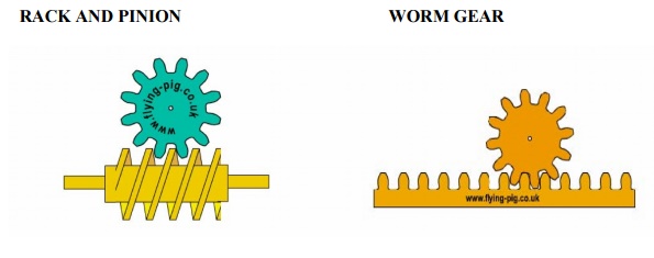
RACK AND PINION: The rack and pinion is used to
convert between rotary and linear motion.
The rack is the flat, toothed part, the pinion is the gear. Rack and pinion
can convert from rotary to linear of from linear to rotary. The diameter of the
gear determines the speed that the rack moves as the pinion turns. Rack and
pinions are commonly used in the steering system of cars to convert the rotary
motion of the steering wheel to the side to side motion in the wheels. Rack and
pinion gears give a positive motion especially compared to the friction drive
of a wheel in tarmac. In the rack and pinion railway a central rack between the
two rails engages with a pinion on the engine allowing the train to be pulled
up very steep slopes.
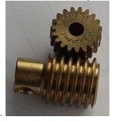
WORM GEAR: A worm is used to reduce speed.
For each complete turn of the worm shaft the gear shaft advances only one tooth of the gear. In this case, with a
twelve tooth gear, the speed is reduced by a factor of twelve. Also, the axis
of rotation is turned by 90 degrees. Unlike ordinary gears, the motion is not
reversible, a worm can drive a gear to reduce speed but a gear cannot drive a
worm to increase it. As the speed is reduced the power to the drive increases
correspondingly. Worm gears are a compact, efficient means of substantially
decreasing speed and increasing power. Ideal for use with small electric
motors.
4 Parallel axis gear trains:
·
Simple Gear Trains – A
simple gear train is a collection of meshing gears where each gear is on
its own axis. The train ratio for a simple gear train is the ratio of the
number of teeth on the input gear to the number of teeth on the output gear. A
simple gear train will typically have 2 or 3 gears and a gear ratio of 10:1 or
less. If the train has 3 gears, the intermediate gear has no numerical effect
on the train ratio except to change the direction of the output gear.
Compound
Gear Trains – A compound gear train is a train where at least
one shaft carries more than one gear. The train ratio is given by the ratio mV =
(product of number of teeth on driver gears)/(product of number of teeth on
driven gears). A common approach to the design of compound gear trains is to
first determine the number of gear reduction steps needed (each step is typically
smaller than 10:1 for size purposes). Once this is done, determine the desired
ratio for each step, select a pinion size, and then calculate the gear size.
·
Reverted Gear Trains – A
reverted gear train is a special case of a compound gear train. A reverted
gear train has the input and output shafts in –line with one another. Assuming
no idler gears are used, a reverted gear train can be realized only if the
number of teeth on the input side of the train adds up to the same as the
number of teeth on the output side of the train.
5 Epicyclic gear trains:
·
If the axis of the shafts over which the gears are
mounted are moving relative to a fixed axis , the gear train is called the
epicyclic gear train.
·
Problems in epicyclic gear trains.
Differentials:
·
Used in the rear axle of an automobile.
·
To enable the rear wheels to revolve at different
speeds when negotiating a curve.
·
To enable the rear wheels to revolve at the same
speeds when going straight.
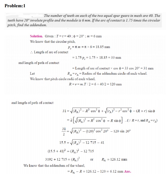
Problem:1
Related Topics