Chapter: Civil : Soil Mechanics -Soil Water And Water Flow
Flow Net (Soil Water)
FLOW NET (Soil Water)
A flow net for an isometric medium is a network of flow lines
and equipotential lines intersecting at right angles to each other. The path
which a particle of water follows in its course of seepage through a saturated
soil mass is called a flow line. Equipotential lines are lines that intersect
the flow lines at right angles. At all points along an equipotential line, the
water would rise in piezometric tubes to the same elevation known as the
piezometric head .
1 LAPLACE EQUATION:
Laplace equation for two
dimensional flows. Assumption
1. The
saturated porous medium is compressible. The size of the pore
space doesn't change with time, regardless of water pressure.
2. The
seeping water flows under a hydraulic gradient which is due only to gravity head
loss,
or Darcy's law for flow through porous medium is valid.
3. There is
no change in the degree of saturation in the zone of soil through which water
seeps and quantity of water flowing into any element of volume is equal to the
quantity which flows out in the same length of time.
4. The
hydraulic boundary conditions of any entry and exit are known
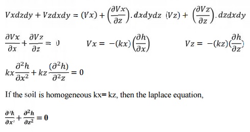
5. Water is incompressible. Consider an element
of soil of size ?x, ?y and of unit thickness perpendicular to the plane of the
paper Let Vx and Vy be the entry velocity components in X and Y directions.
Then (Vs) + (dVx/dx)

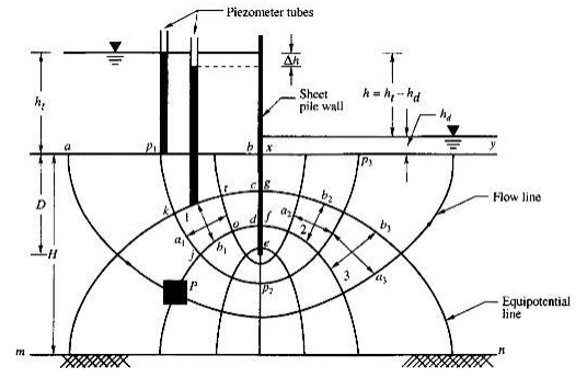
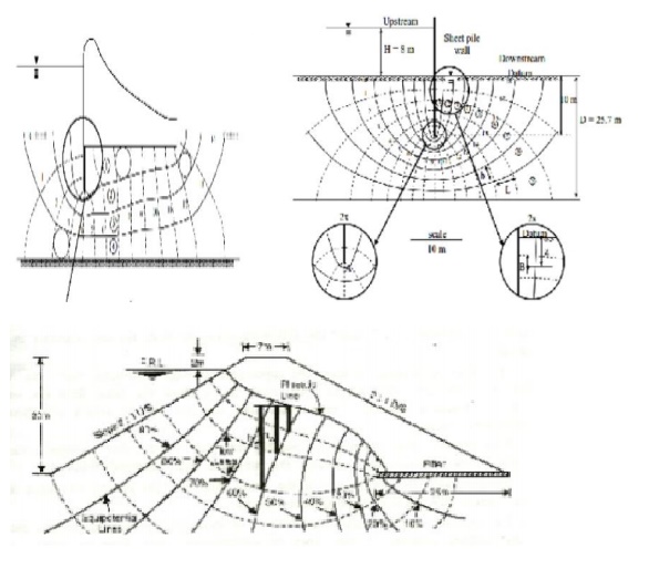
The figure represents a section through an impermeable
diaphragm extending to a depth below the horizontal surface of a homogeneous
stratum of soil of depth H. It is assumed that the difference h between the
water levels on the two sides of the diaphragm is constant. The water enters
the soil on the upstream side of the diaphragm, flows in a downward direction
and rises on the downstream side towards the surface. Consider a
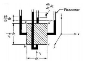
prismatic element P shown shaded in Fig.2.8 which is shown on
a larger scale in 2.9. The element is a parallelepiped with
sides' dx, dy and dz. The x and z directions are as shown in the figure and
the y direction is normal to the section. The velocity v of water which is
tangential to the stream line can be resolved into components vx and vz in the
x and z directions respectively.
ic= ?(??)/(?x)
the hydraulic gradient in the horizontal direction.
iz= ?(? ?)/(? z)
the hydraulic gradient in the vertical direction.
kx = hydraulic conductivity in the horizontal
direction. kz = hydraulic conductivity in the vertical direction.
If we assume that the water and soil are perfectly
incompressible, and the flow is steady, then
the quantity of water that enters the element must
be equal to the quantity that leaves it.
The quantity of water that enters the side ab=vxdzdy
The quantity of water that leaves the side cd = vx
+(?vx/ ?x )dx dy dz
The quantity of water that enters the side bc =
vzdxdy
The quantity of water that leaves side ad = vz+ (?vz/?z)dz dxdy
Therefore, we have the equation,
2 Flow
net Construction:
The graphical method of flow net construction, first given by
Forchheimer (1930), is based on trial sketching. The hydraulic boundary
conditions have a great effect on the general shape of the flow net, and hence
must be examined before sketching is started The flow net can be plotted by
trial and error by observing the following properties of flow net and by
following the practical suggestions given by A. Casagrande.
3
Properties of flow net.
The flow
lines and equipotential lines meet at right angles to one another.
The fields are approximately squares, so that a circle can be
drawn touching all the four sides of the square.
The quantity of water flowing through each flow channel is the
same. Simiary, the same potential drop occur between two successive
equipotential lines.
Smaller the dimensions of the field, greater will be the
hydraulic gradient and velocity of flow through it.
In a homogeneous soil, every transition in the shape of the
curves is smooth, being either elliptical or parabolic in shape.
4 Hints
to draw flow net:
Use every opportunity to study the appearance of well
constructed flow nets. When the picture is sufficiently absorbed in your mind,
try to draw the same flow net without looking at the available solution ;
repeat this until you are able to sketch this flow net in a satisfactory
manner.
Four or five flow channels are usually sufficient for the
first attempts ; the use of too many flow channels may distract the attention
from essential features.
Always watch the appearance of the entire flow net. Do not try
to adjust details before the entire flow net is approximately correct.
The beginner usually makes the mistake of drawing too sharp
transitions between straight and curved sections of flow lines or equipotential
lines. Keep in mind that all transitions are smooth, of elliptical or parabolic
shape. The size of the squares in each channel will change gradually.
5 FLOW
NET FOR VARIOUS WATER RETAINING STRUCTURES
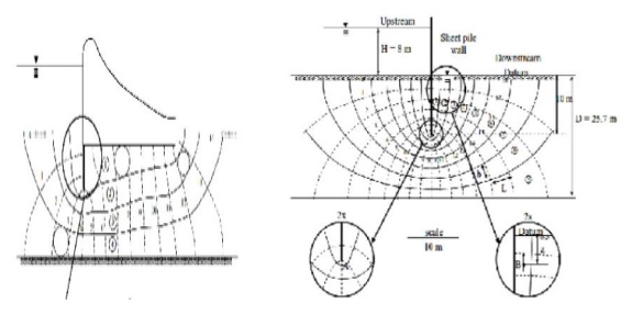
6 Flow
net can be utilized for the following purposes:
Determination of seepage, Determination of hydrostatic
pressure, Determination of seepage pressure, Determination of exit gradient
i.
Determination of seepage
The portion between any two successive flow lines is at flow
channel. The portion ?enclosed
two successive equipotential lines and successive flow lines are known as
field. ?Let b and
l be the width and length of the field.
h = head
drop through the field
q =
discharge passing through the flow channel
H = Total hydraulic head causing flow = difference between
upstream and downstream weeds.
ii.Determination
of hydrostatic pressure.
The
hydrostatic pressure at any point within the soil mass is given by u = h w?w
Where,
u = hydrostatic pressure
hw
= Piezometric head.
The
hydrostatic pressure in terms of
piezometric head hw is calculated from the following relation.
h
w = h- z
iii.Determination
of seepage pressure
The
hydraulic potential h at any point located after N potential drops, each of
value
given
by b ?H = E?h
The
seepage pressure'of any point the hydraulic potential or the balance hydraulic
head multiplied by the unit
Weight
of water, Ps h?w.?Hh
The
pressure acts in the direction flow
iv.Determination
of exit ?gradient.
The
exit gradient is the hydraulic gradient of the downstream end of the flow line
where
the percolating
water leaves the
soil mass and
emerges into free
water at the
downstream.The
exit gradient can be calculated from the following expression, in
h
represents the potential drop and l the average length of last field in the
flow
exit
end.
ie=?h/L
Related Topics