Chapter: Civil : Soil Mechanics -Soil Water And Water Flow
Soil Water: seepage

SEEPAGE
When
water flows through a saturated soil mass, the total head at any point in the
soil mass Consists of (i) piezometric head or pressure head, (ii) the velocity
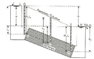
head, and (iii) the position Head. The below shown Figure represents the flow
of water through a saturated soil sample, of length L, due to the difference in
elevation of free water surface at A and B.
At the upper point a of the soil
specimen, piezometric head is (hw) a - At the lower point b,the piezometric
head is (hw)b- At any intermediate point c, the piezometric head hw isequal to
the height through which the water rises in a piezometric tube inserted at that
point.
The piezometric head is also
called the pressure head. A piezometric surface is the linejoining the water
levels in the piezometres. The vertical distance between the
piezometric levels at point 'a' and 'b' is called the
initial hydraulic head H under which the flow takes place.The position or
elevation head at any point is
the elevation of that point with respect to any arbitrary datum. The position
head Z is taken positive if it is situated above the datum andnegative if below
the datum.
A symbol ? is sometimes
used in place of h to represent the hydraulic potential or the potential
function. However, when ? represents a product of k and h, it is known as
the velocity potential.
The loss of head or the
dissipation of the hydraulic head per unit distance of flow through the soil is
called the hydraulic gradient i = h/L . By virtue of the viscous
friction exerted on water flowing through soil pores, an energy transfer is
effected between the water and the soil. The force corresponding to this energy
transfer is called the seepage force or seepage pressure. Thus,
seepage pressure is the pressure exerted by water on the soil through which it
percolates. It is this seepage pressure that is responsible for the phenomenon
known as quick sand and is of vital importance in the stability analysis of
earth structures subjected to the action of seepage.
1 Importance for the study of seepage of water
Determination of rate of settlement of a saturated
compressible soil layer.
Calculation of seepage through the body of earth dams, and
stability of slopes.
Calculation of uplift pressure under hydraulic structure and
there safety against piping.
Ground water flow towards well and drainage of soil
2 Quick Sand Condition:
When flow
takes place in an upward direction, the seepage pressure also acts in the
upward direction and the effective pressure is reduced. If the seepage pressure
becomes equal to the pressure due to submerged weight of the soil, the
effective pressure is reduced to zero. In such a case, cohesion less soil loses
all its shear strength, and the soil particles have a tendency to move up in
the direction of flow. This phenomenon of lifting of soil particles is called
quick condition, boiling condition or quick sand. The hydraulic gradient at
such a critical state is called the critical hydraulic gradient.
For loose deposits of sand or
silt, if voids ratio e is taken as 0.67 and G as 2.67, the critical hydraulic
gradient works out to be unity. It should be noted that quick sand is not a
type of sand but a flow condition occurring within a cohesion less soil when
its effective pressure is reduced to zero due to upward flow of water.
Related Topics