Chapter: Civil : Railway Airport Harbour Engineering : Railway Engineering : Equipment at Railway Stations
Equipment at Railway Stations
Equipment
at Railway Stations
Introduction
A lot of equipment is required at
railway stations and yards for the efficient working of the railway system.
This equipment serves the following purposes.
(a) Providing
facilities for the convenience of passengers-platforms, foot over bridges, and
subways.
(b) Receipt
and dispatch of goods traffic-cranes, weigh bridges, loading gauges, and end
loading ramps.
(c) Equipment
for locomotives and coaches-locomotive sheds, examination pits, ashpits, water
columns, turntables, and triangles.
(d) Isolation
of running lines-and derailing switch, scotch block, sand humps, buffer stops,
and fouling marks.
The
details of some of the important railway equipment are given in this chapter.
1 Platforms
The following types of platforms are provided on Indian
Railways.
Passenger platforms
These are provided to facilitate
the movement of passengers and to help them entrain and detrain. Passenger
platforms can be of three types, namely, rail-level platforms, low-level
platforms, and high-level platforms. These have been discussed in detail in
Chapter 26.
Goods platforms
These platforms are provided for
the loading and unloading of goods and parcels onto and from wagons. The essential
features of these goods platforms are the following.
(a) A goods
platform is normally surfaced with bituminous carpet or concrete. In the case
of light traffic, moorum or water-bound macadam can also be used.
(b) The
height of a goods platform is l.07 m for BG, 0.69 m for MG, and 0.61 m for NG
lines. The height of the platform is measured from the rail level and is such
that the platform surface is flush with the floor of the wagon for the easy
loading and unloading of goods.
(c) Adequate
storage accommodation is provided on goods platforms for the storage of goods
and parcels.
(d) Mobile
cranes or fixed overhead gantry cranes are provided for the handling of bulky
and heavy parcels.
2 Foot Over Bridges and Subways
Foot over bridges are provided
for the movement of passengers and light baggage from one platform to another.
Bulky or heavy goods are taken from one platform to another by means of a
handcarts, which are carried across the tracks near the end of the platform in
order to reach the requisite platform. Some stations are also provided with
subways for the movement of the passengers and goods between platforms.
3 Cranes
Cranes are normally provided in
goods sheds to load and unload bulky or heavy material such as heavy machines
and logs from wagons. These are normally of three types.
Fixed jib crane This
crane is fixed at a convenient location on the goods platform for the
purpose of loading and unloading bulky and heavy goods from wagons.
Mobile crane This
crane is mounted on a wagon or a truck and can be moved anywhere on the
platform as per requirement to load or unload bulky parcels.
Overhead gantry cranes It
consists of two horizontal girders or beams supported on a number of
vertical posts. A travelling platform is fixed in between the two girders,
which is fitted with equipment for hoisting goods and is capable of moving to
and fro on the girders. Wagons or road vehicles are brought under the gantry
for loading and unloading materials.
4 Weigh Bridge
A weigh bridge is used to weigh a
loaded wagon so as to get an idea of the weight of its contents. It is
basically a small length of track on a platform that is supported on beams. The
beams are located in a pit under the track and rest on knife edges attached to
levers. When a wagon is placed on the weigh bridge, its weight is indicated by
a pointer on a graduated disc located in an adjoining structure. A weigh bridge
is normally provided on a siding and not on a through track.
5 Loading Gauge
The loading gauge is the gauge or
profile up to which a vehicle can be loaded in order to maintain a minimum
clearance between the loaded top of the wagon and the underside of a structure
such as a bridge, tunnel, or signal post. The dimensions of the load of the wagon
are kept within the fixed limits by erecting a loading gauge across the track
in the shape of a steel frame, which causes an obstruction if the wagon is
loaded to an extent that exceeds the loading gauge (see in old pages).
Loaded wagons whose dimensions
exceed the normal permissible loads are known as oversized dimensioned
consignments (ODCs). ODC parcels can also be sanctioned up to a certain
level after taking the following precautions.
(a) Trains
carrying ODCs should move at a restricted speed, which is specified for the
purpose.
(b) Such
trains should not move at night.
(c) Train
carrying ODCs should be accompanied by a supervisor whose duty is to ensure the
safely of the train along the route.
6 End Loading Ramps
End loading ramps (Fig. 27.1) are provided to
allow the unloading of the wagons at their rear end. Such ramps are also used
for unloading cars and other mobile vehicles. An end loading ramp has the
following essential features.
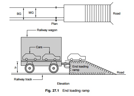
(a) It has a
dead end siding with a buffer stop and a platform with a ramp.
(b) The
platform is at a height of 1.3 m for BG and 0.86 m for MG lines.
(c) A small
gap is maintained between the buffer stop and the ramp platform to minimize the
damage to the platform. This gap is covered by the hinged plates of the wagon
while it is being unloaded.
7 Locomotive Sheds
Locomotive or running sheds are
meant for the maintenance and servicing of locomotives. The location and design
of a locomotive shed depends on the volume and pattern of traffic, the layout
of the terminal station and the marshalling yard, and other allied factors.
Locomotive sheds are normally spaced at about 250 to 300 km apart in order to
avoid the idle movement of locomotives and crew. Locomotive sheds are basically
of two types.
Homing sheds These are
provided to house locomotives and attend to their maintenance and
servicing. Equal stress is laid on the servicing and maintenance of locomotives
in these sheds. These sheds are normally designed to house about 80 to 100
locomotives.
Turn round sheds These are
provided for servicing locomotives and bringing them back to the homing
sheds. They may also be provided for attending to certain minor repairs. These
sheds are normally designed to hold about 30 to 50 locomotives.
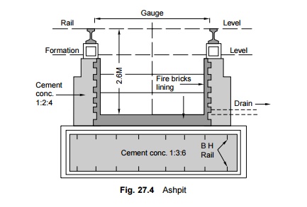
8 Ashpits
Ashpits (also called de-ashing Pits) (Fig. 27.4)
are provided to collect the ashes falling from the locomotives. They are
rectangular in shape and of a depth of about 1 m and are lined with fire
bricks. The length of the ashpits should be adequate so that the longest
locomotive can be de-ashed on the pit. The length is normally 15.9 m (52 ft)
for BG locomotives. The ashpits are suitably sloped from the centre towards the
ends so that water can be drained effectively.
The ashpits should be cleaned as
often as possible. The ashes should first be dumped outside the pit and
subsequently removed and stored at a suitable place for further disposal. The
area around the ashpit should be paved and ample space should be provided for
the picking up and storage of cinder.
Ashpits are normally provided at
those points in the locomotive sheds where the locomotives turn for cleaning or
dropping of fire. These are also provided in big stations at places where the
locomotives collect water for de-ashing.
9 Water Columns
Water columns (Fig. 27.5) are
provided to supply water to the locomotives. A water column consists of a
vertical pipe with a surveilling arm of either a horizontal shape or the shape
of a swan's neck. A bay hose spout is provided at the end of the arm to enable
water to be diverted to the opening in the engine tender. A foot valve is fixed
inside the water column and water is made available from a suitably located
high service tank.
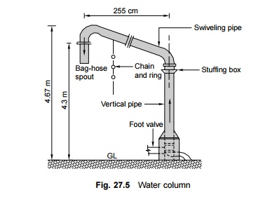
Water columns are provided in
locomotive yards as well as at various stations, where engines are required to
be watered and fuelled.
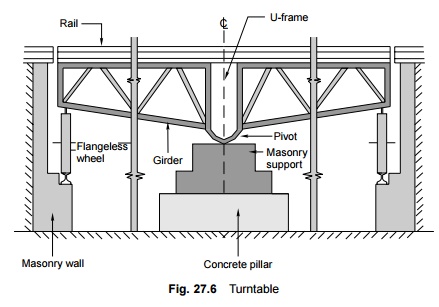
10 Turntable
A turntable (Fig. 27.6) is a
device used for changing the direction of a locomotive. It is normally provided
at terminal stations, locomotive yards, and marshalling yards.
11 Triangles
Triangles are used for reversing
the direction of engines at locations where providing a costly turntable may
not be justified and where the available area is adequate for the provision of
a triangle. Triangles are normally provided at the terminals of short lines.
The details of a triangle are given in Chapter 15.
12 Traverser
This is a device for transferring
vehicles from one track to a parallel one without the use of a turnout or a
crossover. It is quite a costly arrangement and is preferred only in workshops
where space is limited and a coach or locomotive is required to be shifted from
one shop to another on a nominated line.
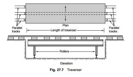
A traverser (Fig. 27.7) consists
of a platform with a track that is mounted on small wheels or rollers, which
can traverse to and fro and can fall in line with the track on either side of
the traverser. The following steps are involved in transferring a vehicle
standing on track 3 on the left-hand side of the traverser to track 2 on the
right-hand side.
1. The traverser
is aligned with track 3 on the left-hand side.
2. The
vehicle is then transferred to the traverser track.
3. The
traverser is then shifted so as the align it with the track on the right-hand
side.
4. The
vehicle is then transferred to track 2 on the right-hand side.
13 Carriage Washing Platforms
Terminal stations are provided
with the facility for washing carriages so that passenger bogies can be cleaned
and washed properly. This consists of two or three long sidings that can
accommodate the entire length of the rake and washing platforms that are
provided between the sidings. The salient features of these washing platforms
are the following.
(a) Washing
platforms are long platforms of a height equal to the height of the carriage
floor that are generally made of cement concrete. In the case of BG lines their
width is about 0.61 m.
(b) The
washing platform is equipped with a number of hydrants for washing the
carriages. An adequate water supply is made available to ensure that the
pressure of the water inside the hydrant is sufficient.
(c) A washing
platform is normally provided between two tracks so that two carriages can be
washed simultaneously.
(d) The
tracks are supported on masonry structures and have adequate arrangement for
the drainage of water.
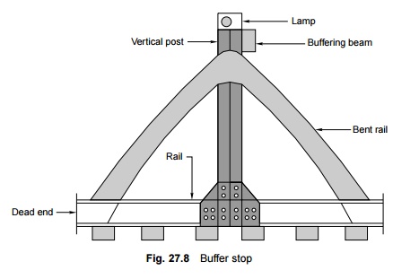
14 Buffer Stop
Buffer stops (Fig. 27.8) or 'snag
dead ends' are provided at the end of a siding to ensure that the vehicles stop
while still on the track and do not go off it. The buffer stop is a type of
barrier placed across the track which stops the vehicles from going beyond the
selected point. Its essential features are the following.
(a) The
buffer stop should be structurally strong to take the impact of a rolling
vehicle.
(b) It should
have a buffer disc with a cross-sleeper, which is normally painted red. A red
lamp should be provided at its centre for night indication.
(c) Normally
the track should be straight for some distance near the buffer stop.
(d) It should
be visible from a long distance.
15 Scotch Block, Derailing Switch, and
Sand Hump
It is normal practice to isolate
a through running line from a siding so that a vehicle standing on the siding
does not accidentally roll onto the running line and foul the same. A scotch
block or derailing switch is provided on a siding or shunting neck to ensure
that the vehicle does not go beyond a particular point and that if this
happens, the vehicle gets derailed.
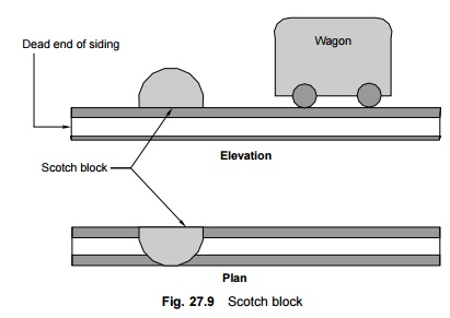
Scotch block A scotch
block (Fig. 27.9) is a wooden block placed on the rail and properly held
in its place with the help of a device to form an obstruction. Once it is
clamped in position, the scotch block does not allow a vehicle to move beyond
it.
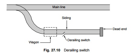
Derailing switch A
derailing switch (Fig. 27.10) consists of a half-switch, i.e., only a
tongue rail, which in its open position faces away from the stock rail, leaving
a gap in between, and this causes a discontinuity in the track. A vehicle
cannot go beyond this point and gets automatically derailed if it does manage
to do so. The switch can be closed with the help of a lever and a vehicle can
then traverse it normally. This is also called a trap switch.
Sand hump This is
possibly the most improved method of isolating and stoping a moving
vehicle without causing much damage to it. The sand hump (Fig 27.11) is normally
provided on the loop line with the idea that in case an incoming train
overshoots when being received on the loop line, the sand hump can make it stop
while ensuring that there is least damage to it.
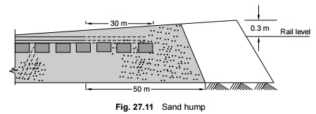
A sand hump consists of a mound
of sand of a specified cross section that covers the track under the end of a
dead end siding, which is laid on a rising gradient. A moving vehicle comes to
a stop because of the combined resistance of the sand hump and the rising
gradient.
16 Fouling Mark
A fouling mark (Fig. 27.12) is
provided between two converging tracks at the point beyond which the
centre-to-centre distance of the track is less than the stipulated minimum
distance. This minimum distance is 4.265 m for BG and 3.66 m for MG lines. A
vehicle standing on a loop line is not stabled beyond the fouling mark,
otherwise it may have a side collision with the vehicle standing on the main
line. The salient features of a fouling mark are as follows.
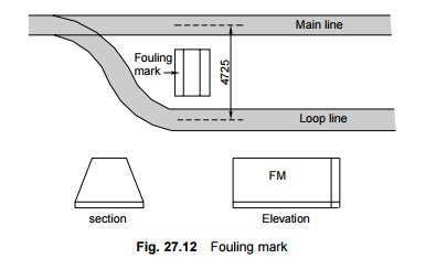
(a) A fouling
mark consists of a stone or concrete block or an old wooden or steel sleeper
painted white.
(b) The
fouling mark should be visible from a distance. Therefore, it is painted white
and has the letters FM marked on it in bold using black paint.
(c) The top
of the fouling mark should be in line with the top of the ballast section.
(d) The
fouling mark should be fixed firmly on the ground at right angles to the track.
Related Topics