Chapter: Fundamentals of Database Systems : Conceptual Modeling and Database Design : Data Modeling Using the Entity-Relationship (ER) Model
ER Diagrams, Naming Conventions, and Design Issues
ER Diagrams, Naming Conventions, and Design Issues
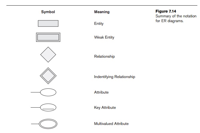
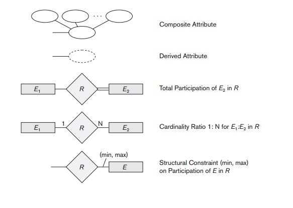
1. Summary of Notation
for ER Diagrams
Figures 7.9 through 7.13 illustrate examples of the participation of
entity types in relationship types by displaying their sets or extensions—the
individual entity instances in an entity set and the individual relationship
instances in a relationship set. In ER diagrams the emphasis is on representing
the schemas rather than the instances. This is more useful in database design
because a database schema changes rarely, whereas the contents of the entity
sets change frequently. In addition, the schema is obviously easier to display,
because it is much smaller.
Figure 7.2 displays the COMPANY ER database schema as an ER diagram. We now review the full ER diagram notation. Entity types such as EMPLOYEE, DEPARTMENT, and PROJECT are shown in rectangular boxes. Relationship types such as WORKS_FOR, MANAGES, CONTROLS, and WORKS_ON are shown in diamond-shaped boxes attached to the participating entity types with straight lines. Attributes are shown in ovals, and each attribute is attached by a straight line to its entity type or relationship type. Component attributes of a composite attribute are attached to the oval representing the composite attribute, as illustrated by the Name attribute of EMPLOYEE. Multivalued attributes are shown in double ovals, as illustrated by the Locations attribute of DEPARTMENT. Key attributes have their names underlined. Derived attributes are shown in dotted ovals, as illustrated by the Number_of_employees attribute of DEPARTMENT.
Weak entity types are distinguished by being placed in double rectangles
and by having their identifying relationship placed in double diamonds, as
illustrated by the DEPENDENT entity type and the DEPENDENTS_OF identifying relationship type. The partial key of the weak entity type
is underlined with a dotted line.
In Figure 7.2 the cardinality ratio of each binary relationship type is specified by attaching a 1, M, or N on each participating edge. The cardinality ratio of DEPARTMENT:EMPLOYEE in MANAGES is 1:1, whereas it is 1:N for DEPARTMENT: EMPLOYEE in WORKS_FOR, and M:N for WORKS_ON. The participation constraint is specified by a single line for partial participation and by double lines for total participation (existence dependency).
In Figure 7.2 we show the role names for the SUPERVISION relationship type because the same EMPLOYEE entity
type plays two distinct roles in that relationship. Notice that the cardinality
ratio is 1:N from supervisor to supervisee because each employee in the role of
supervisee has at most one direct supervisor, whereas an employee in the role
of supervisor can supervise zero or more employees.
Figure 7.14 summarizes the conventions for ER diagrams. It is important
to note that there are many other alternative diagrammatic notations (see
Section 7.7.4 and Appendix A).
2. Proper Naming of
Schema Constructs
When designing a database schema, the choice of names for entity types,
attributes, relationship types, and (particularly) roles is not always
straightforward. One should choose names that convey, as much as possible, the
meanings attached to the different constructs in the schema. We choose to use singular names for entity types, rather
than plural ones, because the entity type name applies to each individual
entity belonging to that entity type. In our ER diagrams, we will use the
convention that entity type and relationship type names are uppercase letters,
attribute names have their initial letter capitalized, and role names are
lowercase letters. We have used this convention in Figure 7.2.
As a general practice, given a narrative description of the database
requirements, the nouns appearing in
the narrative tend to give rise to entity type names, and the verbs tend to indicate names of
relationship types. Attribute names generally arise from additional nouns that
describe the nouns corresponding to entity types.
Another naming consideration involves choosing binary relationship names
to make the ER diagram of the schema readable from left to right and from top
to bot-tom. We have generally followed this guideline in Figure 7.2. To explain
this naming convention further, we have one exception to the convention in
Figure 7.2—the DEPENDENTS_OF
relationship type, which reads from bottom to top.
When we
describe this relationship, we can say that the DEPENDENT entities (bottom entity type) are DEPENDENTS_OF
(relationship name) an EMPLOYEE (top entity type). To change
this to read from top to bottom, we could rename the relationship type to HAS_DEPENDENTS, which would then read as follows: An EMPLOYEE entity
(top entity type) HAS_DEPENDENTS (relationship name) of type DEPENDENT (bottom entity type). Notice that this issue arises because each binary
relationship can be described starting from either of the two participating
entity types, as discussed in the beginning of Section 7.4.
3. Design Choices for ER
Conceptual Design
It is occasionally difficult to decide whether a particular concept in
the miniworld should be modeled as an entity type, an attribute, or a
relationship type. In this
section, we give some brief guidelines as to which construct should be
chosen in particular situations.
In general, the schema design process should be considered an iterative
refinement process, where an initial design is created and then iteratively
refined until the most suitable design is reached. Some of the refinements that
are often used include the following:
A concept may be first modeled as
an attribute and then refined into a rela-tionship because it is determined that
the attribute is a reference to another entity type. It is often the case that
a pair of such attributes that are inverses of one another are refined into a
binary relationship. We discussed this type of refinement in detail in Section
7.6. It is important to note that in our notation, once an attribute is
replaced by a relationship, the attribute itself should be removed from the
entity type to avoid duplication and redundancy.
Similarly, an attribute that
exists in several entity types may be elevated or promoted to an independent
entity type. For example, suppose that several entity types in a UNIVERSITY database, such as STUDENT, INSTRUCTOR, and COURSE, each has an attribute Department in the initial design; the
designer
may then choose to create an entity type DEPARTMENT with a
single attribute Dept_name and relate it to the three entity types (STUDENT, INSTRUCTOR, and
COURSE) via appropriate relationships.
Other attributes/relationships of DEPARTMENT may be
discovered later.
An inverse refinement to the
previous case may be applied—for example, if an entity type DEPARTMENT exists in the initial design with a single attribute Dept_name and is related to only one other entity type, STUDENT. In this
case, DEPARTMENT may be
reduced or demoted to an attribute of STUDENT.
Section 7.9 discusses choices
concerning the degree of a relationship. In Chapter 8, we discuss other
refinements concerning specialization/general-ization. Chapter 10 discusses
additional top-down and bottom-up refinements that are common in large-scale
conceptual schema design.
4. Alternative Notations for ER Diagrams
There are many alternative diagrammatic notations for displaying ER
diagrams. Appendix A gives some of the more popular notations. In Section 7.8,
we introduce the Unified Modeling Language (UML) notation for class diagrams,
which has been proposed as a standard for conceptual object modeling.
In this section, we describe one alternative ER notation for specifying
structural constraints on relationships, which replaces the cardinality ratio
(1:1, 1:N, M:N) and single/double line notation for participation constraints.
This notation involves associating a pair of integer numbers (min, max) with
each participation of an entity type E in a relationship type R, where 0 ≤ min ≤ max and
max ≥ 1. The num-bers mean that for each entity e in E, e must participate in at least min and
at most max relationship instances in R
at any point in time. In this method, min = 0 implies partial
participation, whereas min > 0 implies total participation.
Figure 7.15 displays the COMPANY database
schema using the (min, max) notation. Usually, one uses either the cardinality
ratio/single-line/double-line notation or
the (min, max) notation. The (min, max)
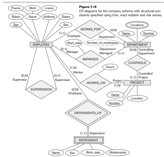
notation is more precise, and we can use it to specify some structural
constraints for relationship types of higher
degree. However, it is not sufficient for specifying some key constraints
on higher-degree relationships, as discussed in Section 7.9.
Figure 7.15 also displays all the role names for the COMPANY database schema.
Related Topics