Chapter: Design of Electrical Machines : Induction Motors
Design of Stator - Induction Motors
Design of Stator
Stator of an induction motor consists of stator core and stator slots.
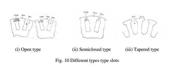
Stator slots: in general two types of stator slots are employed in induction motors viz, open clots and semiclosed slots. Operating performance of the induction motors depends upon the shape of the slots and hence it is important to select suitable slot for the stator slots.
(i) Open slots: In this type of slots the slot opening will be equal to that of the width of the slots as shown in Fig 10. In such type of slots assembly and repair of winding are easy. However such slots will lead to higher air gap
contraction factor and hence poor power factor. Hence these types of slots are rarely used in 3Φ induction motors.
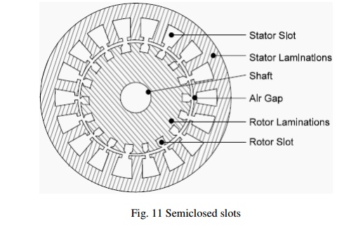
(ii) Semiclosed slots: In such type of slots, slot opening is much smaller than the width of the slot as shown in Fig 10 and Fig 11. Hence in this type of slots assembly of windings is more difficult and takes more time compared to open slots and hence it is costlier. However the air gap characteristics are better compared to open type slots.
(iii) Tapered slots: In this type of slots also, opening will be much smaller than the slot width. However the slot width will be varying from top of the slot to bottom of the slot with minimum width at the bottom as shown in Fig. 10.
Selection of number of stator slots: Number of stator slots must be properly selected at the design stage as such this number affects the weight, cost and operating characteristics of the motor. Though there are no rules for selecting the number of stator slots considering the advantages and disadvantages of selecting higher number slots comprise has to be set for selecting the number of slots. Following are the advantages and disadvantages of selecting higher number of slots.
Advantages :(i) Reduced leakage reactance.
(ii) Reduced tooth pulsation losses.
(iii) Higher over load capacity.
Disadvantages:
(i) Increased cost
(ii) Increased weight
(iii) Increased magnetizing current
(iv) Increased iron losses
(v) Poor cooling
(vi) Increased temperature rise
(vii) Reduction in efficiency
Based on the above comprise is made and the number of slots/pole/phase may be selected as three or more for integral slot winding. However for fractional slot windings number of slots/pole/phase may be selected as 3.5. So selected number of slots should satisfy the consideration of stator slot pitch at the air gap surface, which should be between1.5 to 2.5 cm.
Stator slot pitch at the air gap surface = τss= πD/Sss where Sss is the number of stator slots
Turns per phase
EMF equation of an induction motor is given by Eph = 4.44fΦTphkw
Hence turns per phase can be obtained from emf equation Tph = Eph/ 4.44fΦkw
Generally the induced emf can be assumed to be equal to the applied voltage per phase
Flux/pole, = Bav x πDL/P,
winding factor kw may be assumed as 0.955 for full pitch distributed winding unless otherwise specified.
Number conductors /phase, Zph = 2 x Tph, and hence Total number of stator conductors Z = 6 Tph and conductors /slot Zs = Z/Ss or 6 Tph/Ss , where Zsis an integer for single layer winding and even number for double layer winding.
Conductor cross section: Area of cross section of stator conductors can be estimated from the stator current per phase and suitably assumed value of current density for the stator windings.
Sectional area of the stator conductor as = Is / δs where δs is the current density in stator windings
Stator current per phase Is = Q / (3Vph cos ϕ )
A suitable value of current density has to be assumed considering the advantages and disadvantages.
Advantages of higher value of current density:
(i) reduction in cross section
(ii) reduction in weight
(iii) reduction in cost
Disadvantages of higher value of current density
(i) increase in resistance
(ii) increase in cu loss
(iii) increase in temperature rise
(iv) reduction in efficiency
Hence higher value is assumed for low voltage machines and small machines. Usual value of current density for stator windings is 3 to 5 amps.
Based on the sectional area shape and size of the conductor can be decided. If the sectional area of the conductors is below 5 mm2 then usually circular conductors are employed. If it is above 5 mm2 then rectangular conductors will be employed. Standard bare size of round and rectangular conductors can be selected by referring the tables of conductors given in Design data Hand book. In case of rectangular conductors width to thickness ratio must be between 2.5 to 3.5.
Area of stator slot: Slot area is occupied by the conductors and the insulation. Out of which almost more than 25 % is the insulation. Once the number of conductors per slot is decided approximate area of the slot can be estimated.
Slot space factor = Copper area in the slot /Area of each slot
This slot space factor so obtained will be between 0.25 and 0.4. The detailed dimension of the slot can be estimated as follows.
Size of the slot: Normally different types of slots are employed for carrying stator windings of induction motors. Generally full pitched double layer windings are employed for stator windings. For double layer windings the conductor per slot will be even. These conductors are suitably arranged along the depth and width of the winding. Stator slots should not be too wide, leading to thin tooth width, which makes the tooth mechanically weak and maximum flux density may exceed the permissible limit. Hence slot width should be so selected such that the flux density in tooth is between 1.6 to 1.8 Tesla. Further the slots should not be too deep also other wise the leakage reactance increases. As a guideline the ratio of slot depth to slot width may assumed as 3 to 5. Slot insulation details along the conductors are shown in Fig. 12.
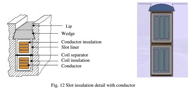
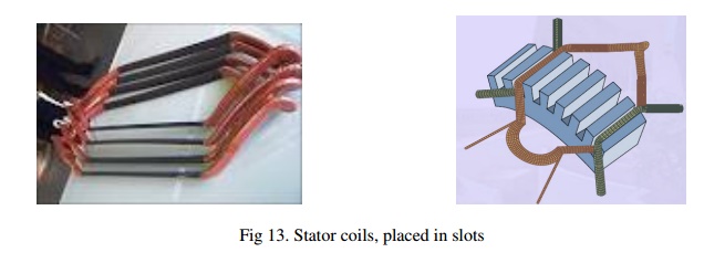
Proper slot insulation as per the voltage rating of the machine has to be provided before inserting the insulated coil in the slots. This slot insulation is called the slot liner, thickness of which may be taken as 0.5 mm to 0.7 mm. Suitable thickness of insulation called coil separator separates the two layers of coils. Thickness of coil separator is 0.5 mm to 0.7 mm for low voltage machines and 0.8 mm to 1.2 mm for high voltage machines. Wedge of suitable thickness (3.5 mm to 5 mm) is placed at the top of the slot to hold the coils in position. Lip of the slot is taken 1.0 to 2.0 mm. Figure 13 shows the coils placed in slots.
Length of the mean Turn:
Length of the mean turn is calculated using an empirical formula lmt = 2L + 2.3 τp + 0.24 where L is the gross length of the stator and τp is pole pitch in meter.
Resistance of stator winding: Resistance of the stator winding per phase is calculated using the formula = (0.021 x lmt x Tph ) / as where lmt is in meter and as is in mm2. Using so calculated resistance of stator winding copper losses in stator winding can be calculated as
Total copper losses in stator winding = 3 (Is)2 rs
Flux density in stator tooth: Knowing the dimensions of stator slot pitch, width of the slot and width of the stator tooth flux density in the stator tooth can be calculated. The flux density in the stator tooth is limited to 1.8 Tesla. As the stator tooth is tapering towards the bottom, the flux density is calculated at 1/3rd height from the narrow end of the tooth. The flux density at the 1/3rd height from the narrow end of the tooth can be calculated as follows.
Diameter at 1/3rd height from narrow end D' = D + 1/3 x hts x 2
Slot pitch at 1/3rd height = τ's = π x D' /Ss
Tooth width at this section = b't = τ's – bs
Area of one stator tooth = a't = b't x li
Area of all the stator tooth per pole A't = b't x li x number of teeth per pole
Mean flux density in stator teeth B't = Φ / A't
Maximum flux density in the stator teeth may be taken to be less than 1.5 times the above value.
Depth of stator core below the slots: There will be certain solid portion below the slots in the stator which is called the depth of the stator core. This depth of the stator core can be calculated by assuming suitable value for the flux density Bc in the stator core. Generally the flux density in the stator core may be assumed varying between 1.2 to 1.4 Tesla. Depth of the stator core can be calculated as follows.
Flux in the stator core section Φc = ½ Φ
Area of stator core Ac = Φ/2Bc
Area of stator core Ac = Li x dcs
Hence, depth of the core = Ac / Li
Using the design data obtained so far outer diameter of the stator core can be calculated as
Do = D + 2hss = 2 dcs where hss is the height of the stator slot.
Related Topics