Chapter: Digital Principles and System Design : Asynchronous Sequential Circuits
Design Procedure of Asynchronous Sequential circuits
DESIGN PROCEDURE
There are a number of steps that must be carried out in order
to minimize the circuit complexity and to produce a stable circuit without
critical races. Briefly, the design steps are as follows:
Ø Obtain a primitive flow table from the given
specification.
Ø Reduce
the flow table by merging rows in the primitive flow table.
Ø Assign
binary states variables to each row of the reduced flow table to obtain the
transition table.
Ø Assign
output values to the dashes associated with the unstable states to obtain the output
maps.
Ø Simplify
the Boolean functions of the excitation and output variables and draw the logic
diagram.
The design process will be demonstrated by going through a
specific example:
Design Example –
Specification
Design a gated latch circuit with
two inputs, G (gate) and D (data), and one output Q. The gated latch is a
memory element that accepts the value of D when G = 1 and retains this value
after G goes to 0. Once G = 0, a change in D does not change the value of the
output Q.
ü Step 1: Primitive Flow Table
A primitive flow table is a flow
table with only one stable total state in each row. The total state consists of
the internal state combined with the input.
To derive the primitive flow
table, first a table with all possible total states in the system is needed:
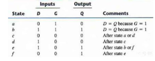
Each row in the above table
specifies a total state; the resulting primitive table for the gated latch is
shown below:
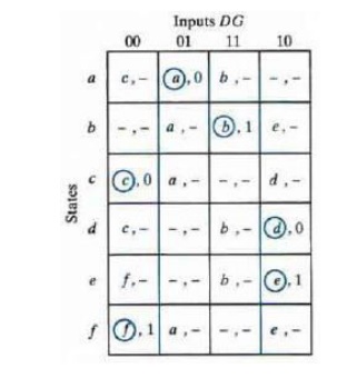
First, we fill in one square in
each row belonging to the stable state in that row. Next recalling that both
inputs are not allowed to change at the same time, we enter dash marks in each
row that differs in two or more variables from the input variables associated
with the stable state. Next we find values for two
more squares in each row. The
comments listed in the previous table may help in deriving the necessary
information. A dash indicates don’t care conditions.
ü Step 2: Reduction of the Primitive Flow Table
The primitive flow table can be
reduced to a smaller number of rows if two or more stable states are placed in
the same row of the flow table. The simplified merging rules are as follows:
Ø Two or
more rows in the primitive flow table can be merged into one if there are non-
conflicting states and outputs in each of the columns.
Ø Whenever,
one state symbol and don’t care entries are encountered in thethesamestate column, is listed in the merged row.
Ø If the
state is circled in one of the rows, it is also circled in the merged row.
Ø The
output state is included with each stable state in the merged row.
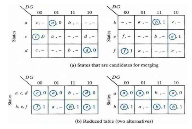
Now apply these rules to the
primitive flow table shown previously. To see how this is done the primitive
flow table is separated into two parts of three rows each:
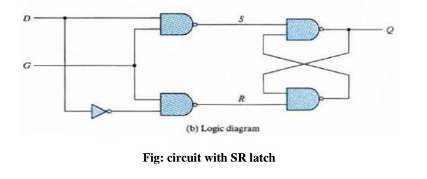
ü Step 3: Transition table and logic diagram
The assignment of distinct binary
value to each state converts the flow table into a transition table. In the
general case, a binary state assignment must be made to ensure that the circuit
will be free of critical races. There can be no critical races in a two-row
flow table; therefore, we can finish the design of the gated latch. Assigning 0
to state a and 1 to state b in the reduced flow table, we obtain
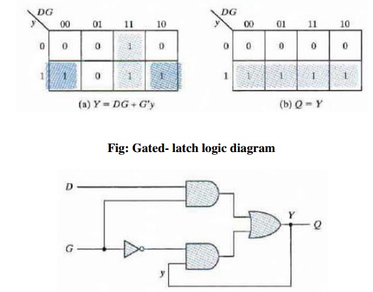
the transition table. The transition table is, in effect, a map for the
excitation variable Y. The simplified Boolean function for Y is then obtained
from the map.

ü Step 4: Assigning Outputs to Unstable States
The stable states in a flow table have specific output values associated with them. The unstable states have unspecified output entries designated by a dash. The output values for the unstable states must be chosen so that no momentary false outputs occur when the circuit switches between stable states. This means that if an output variable is not supposed to change as the result of a transition. then an unstable state that is a transient state between two stable states must have the same output value as the stable states.
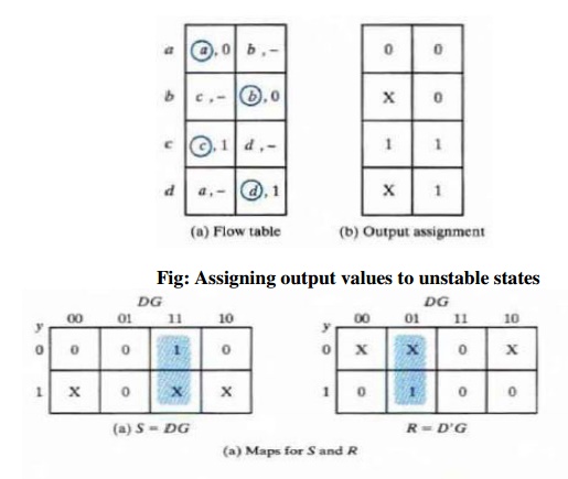
If an output variable is 10 change value as a result of a
change in state, then this variable is assigned a don’
-tcare
condition. If a 0 is entered as the output value for the unstable state c, then
the change in the output variable will not take
place until the end of the transition. If a 1 is entered, the change will take
place at the start of the transition, since it makes no difference, Reduction
of State and Flow tables when the change in output occurs, we place a
don't-care entry for the output associated with unstable state.
Related Topics