Chapter: Special Electrical Machines : Synchronous Reluctance Motors
Construction of Synchronous Reluctance Motor
CONSTRUCTION OF SYNCHRONOUS
RELUCTANCE MOTOR
The
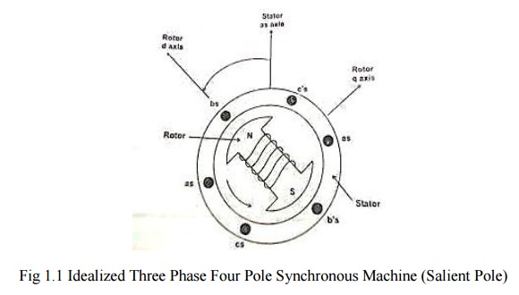
structure of reluctance motor is same as that of salient pole synchronous
machine as shown in fig. The rotor does not have any field winding .The stator
has three phase symmetrical winding, which creates sinusoidal rotating magnetic
field in the air gap, and the reluctance torque is developed because the
induced magnetic field in the rotor has a tendency to cause the rotor to align
with the stator field at a minimum reluctance position
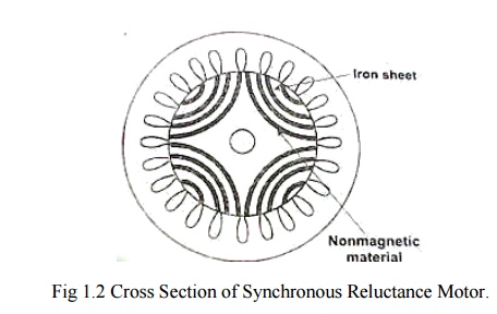
The rotor
of the modern reluctance machine is designed with iron laminations in the axial
direction separated by non-magnetic material. The performance of the reluctance
motor may approach that of induction machine. With high saliency ratio a power
factor oh 0.8 can be reached. The efficiency of a reluctance machine may be
higher than an induction motor because there is no rotor copper loss. Because
of inherent simplicity, robustness of construction and low cost.
The
synchronous reluctance motor has no synchronous starting torque and runs up
from stand still by induction action. There is an auxiliary starting winding.
This has increased the pull out torque, the power factor and the efficiency.
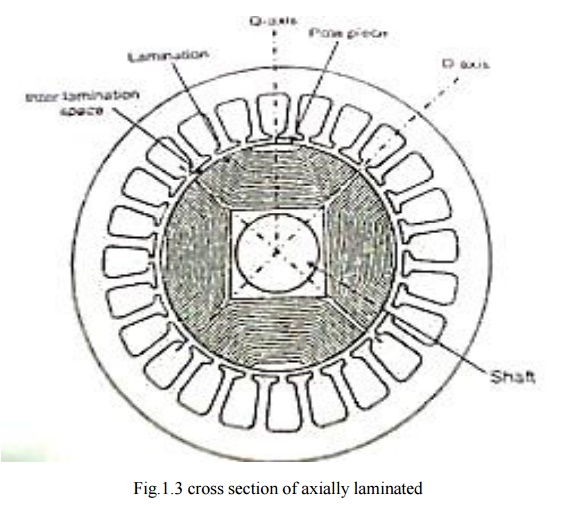
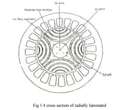
Synchronous
reluctance motor is designed for high power applications. It can broadly be
classified into
Axially
laminated and
Radially
laminated.
Reluctance
motors can deliver very high power density at low cost, making them ideal for
many applications. Disadvantages are high torque ripple (the difference between
maximum and minimum torque during one revolution) when operated at low speed,
and noise caused by torque ripple. Until the early twenty-first century their
use was limited by the complexity of designing and controlling them. These
challenges are being overcome by advances in the theory, by the use of
sophisticated computer design tools, and by the use of low-
cost
embedded systems for control, typically based on microcontrollers using control
algorithms and real-time computing to tailor drive waveforms according to rotor
position and current or voltage feedback. Before the development of large-scale
integrated circuits the control electronics would have been prohibitively
costly.
The
stator consists of multiple projecting (salient) electromagnet poles, similar
to a wound field brushed DC motor. The rotor consists of soft magnetic
material, such as laminated silicon steel, which has multiple projections
acting as salient magnetic poles through magnetic reluctance. The number of
rotor poles is typically less than the number of stator poles, which minimizes
torque ripple and prevents the poles from all aligning simultaneously—a
position which cannot generate torque.
When a
rotor pole is equidistant from the two adjacent stator poles, the rotor pole is
said to be in the "fully unaligned position". This is the position of
maximum magnetic reluctance for the rotor pole. In the "aligned
position", two (or more) rotor poles are fully aligned with two (or more)
stator poles, (which mean the rotor poles completely face the stator poles) and
is a position of minimum reluctance.
When a
stator pole is energized, the rotor torque is in the direction that will reduce
reluctance. Thus the nearest rotor pole is pulled from the unaligned position
into alignment with the stator field (a position of less reluctance). (This is
the same effect used by a solenoid, or when picking up ferromagnetic metal with
a magnet.) In order to sustain rotation, the stator field must rotate in
advance of the rotor poles, thus constantly "pulling" the rotor
along. Some motor variants will run on 3-phase AC power (see the synchronous
reluctance variant below). Most modern designs are of the switched reluctance type,
because electronic commutation gives significant control advantages for motor
starting, speed control, and smooth operation (low torque ripple).
Dual-rotor
layouts provide more torque at lower price per volume or per mass. [The
inductance of each phase winding in the motor will vary with position, because
the reluctance also varies with position. This presents a control systems
challenge.
Applications
v Some washing
machine designs.
v Control
rod drive mechanisms of nuclear reactors.
v The Dyson Digital Motor used in some
products produced by the Dyson company.
Related Topics