Chapter: Linear Integrated Circuits : Analog Multiplier and PLL
Analog Multiplier ICs
Analog
Multiplier ICs
Analog
multiplier is a circuit whose output voltage at any instant is proportional to
the product of instantaneous value of two individual input voltages.
Important
applications of these multipliers are multiplication, division, squaring and
square – rooting of signals, modulation and demodulation.
These
analog multipliers are available as integrated circuits consisting of op-amps
and other circuit elements. The Schematic of a typical analog multiplier,
namely, AD633 is shown in figure.
·
The
AD633 multiplier is a four – quadrant analog multiplier.
·
It
possesses high input impedance; this characteristic makes the loading effect on
the signal source negligible.
·
It
can operate with supply voltages ranging from ±18V.
·
IC
does not require external components.
·
The
typical range of the two input signals is ±10V.
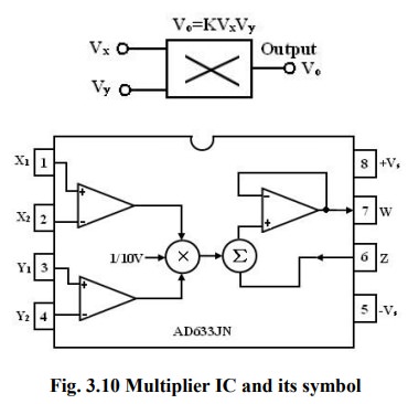
Schematic
representation of a multiplier:
The
schematic representation of an analog multiplier is shown in figure. The output
V0 is the product of the two inputs Vx and Vy
is divided by a reference voltage Vref. Normally, the reference
voltage Vref is internally set to 10V. Therefore, V0 =VxVy/10.
In other words, the basic input – output relationship can be defined by KVx
Vy when K = 1/10, a constant. Thus for peak input voltages of 10V,
the peak magnitude of output voltage is 1/10 *10 *10 =10V. Thus, it can be
noted that, as long as Vx < 10V and Vy < 10V, the
multiplier output will not saturate.
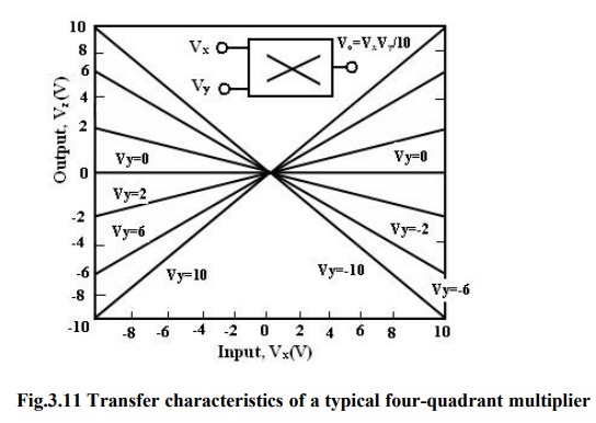
Multiplier quadrants:
The
transfer characteristics of a typical four-quadrant multiplier are shown in
figure. Both the inputs can be positive or negative to obtain the corresponding
output as shown in the transfer characteristics.
Applications of Multiplier ICs:
The
multiplier ICs are used for the following purposes:
1.
Voltage
Squarer
2.
Frequency
doublers
3.
Voltage
divider
4.
Square
rooter
5.
Phase
angle detector
6.
Rectifier
Voltage Squarer:
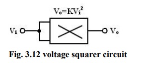
Figure
shows the multiplier IC connected as a squaring circuit. The inputs can be
positive or negative, represented by any corresponding voltage level between 0
and 10V. The input voltage Vi to be squared is simply connected to
both the input terminals, and hence we have, Vx = Vy = Vi
and the output is V0 = KVi2. The circuit thus performs the squaring operation.
This application can be extended for frequency doubling applications.
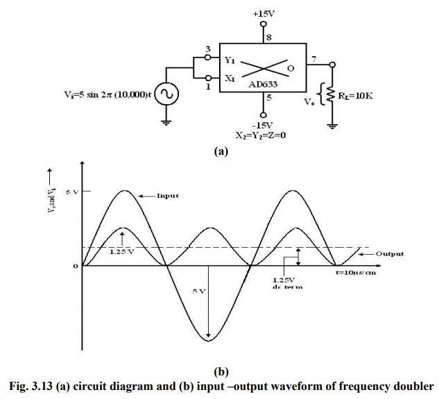
Frequency doublers:
Figure
shows the squaring circuit connected for frequency doubling operation. A
sine-wave signal Vi has a peak amplitude of Av and frequency of f Hz. Then, the
output voltage of the doublers circuit is
given by
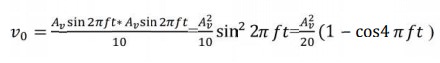
Assuming
a peak amplitude Av of 5V and frequency f of 10KHz, V0 =1.25–1.25 cos2 20000)
t. The first term represents the dc term of 1.25V peak amplitude. The input and
output waveforms are shown in figure. The output waveforms ripple with twice
the input frequency in the rectified output of the input signal. This forms the
principle of application of analog multiplier as rectifier of ac signals.
The
dc component of output V0 can be removed by connecting a 1µF
coupling capacitor between the output terminal and a load resistor, across
which the output can be observed.
Voltage Divider:
In
voltage divider circuit the division is achieved by connecting the multiplier
in the feedback loop of an op-amp.
The
voltages Vden and Vnum represent the two input voltages,
Vdm forms one input of the multiplier, and output of op-amp VoA forms the
second input.
The
output VOA forms the second input. The output VOM of the multiplier
is connected back of op- amp in the feedback loop. Then the characteristic
operation of the multiplier gives
Vom
= KVOA Vdm (1)
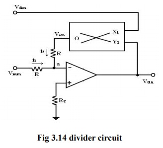
As
shown in figure, no input signal current can flow into the inverting input
terminal of op-amp, which is at virtual ground. Therefore, at the junction a, i1
+ i2 =0, the current i1 = Vnum / R, where R is the input
resistance and the current i2 = Vom /R. With virtual
ground existing at a,
i1+i2
= Vnum / R + Vom /R = 0
KVOA Vden = -
Vnum
or
voA=- vnum/Kvden
where
Vnum and Vden are the numerator and
denominator voltages respectively. Therefore, the voltage division operation is
achieved. Vnum can be a
positive or negative voltage and Vden
can have only positive values to ensure negative feedback. When Vdm is changed, the gain 10/Vdm changes, and
this feature is used in automatic gain control (AGC) circuits.
Square Rooter:
The
divider voltage can be used to find the square root of a signal by connecting
both inputs of the multiplier to the output of the op-amp. Substituting equal in magnitude but opposite in polarity (with
respect to ground) to Vi. But we know that Vom is one- term (Scale factor) of
V0 * V0 or -Vi = Vom = V2/1 0
Solving
for V0 and eliminating √-1 yields. V0 = √10|Vi |
Eqn.
states that V0 equals the
square root of 10 times the absolute magnitude of Vi.
The
input voltage Vi must be negative, or else, the op-amp saturates.
The
range of Vi is between -1 and -10V. Voltages less than -1V will cause
inaccuracies in the result.
The
diode prevents negative saturation for positive polarity Vi signals. For
positive values of Vi the diode connections are reversed.
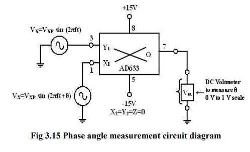
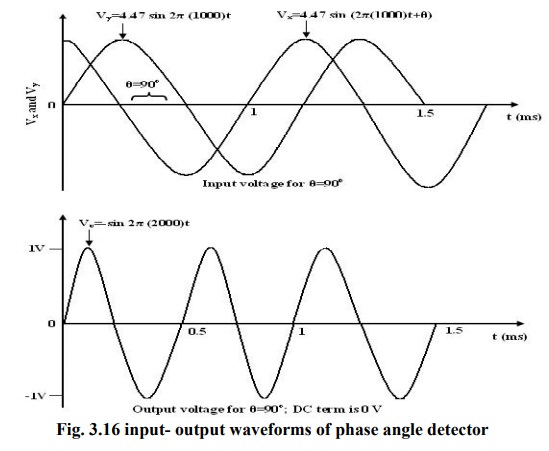
Phase Angle detector:
The
multiplier configured for phase angle detection measurement is shown in figure.
When two sine-waves of the same frequency are applied to the inputs of the
multiplier, the output V0 has a dc component and an AC component.
The
trigonometric identity shows that Sin A sin B =1/2 (cos (A-B) – cos (A+B)).
When
the two frequencies are equal, but with different phase angles, e.g. A=2πft +θ
for signal Vx and B= 2πft for signal Vy, then using the identity
[sin
(2 ft+ )][sin2 ft)]=1/2[cos -cos(4 ft + )]=1/2(dc- the double frequency term)
Therefore,
when the two input signals Vx and Vy are applied to the
multiplier, V0 (dc) is given by
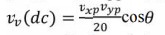
where
Vxp and Vyp are the peak voltage amplitudes of the
signals Vx and Vy. Thus, the output V0(dc)
depends on the factor cos θ. A dc voltmeter can be calibrated as a phase angle
meter when the product of Vxp and Vyp is made equal to
20. Then, a (0-1) V range dc voltmeter can directly read cos θ, with the meter
calibrated directly in degrees from a cosine table. The input and output
waveforms are shown in figure.
Then
the above eqn becomes V0 (dc) = cos θ, if we make the product Vxp
Vyp = 20 or in other words, Vxp – Vyp = 4.47V.
Related Topics