Chapter: Civil : Environmental Engineering : Sewer Design
sewers Design Procedures

Sewers Design Procedures
Layout the sewer: Draw a
line to represent the proposed sewer in each street or alley to be served.
Near of on the line; indicate by an arrow the direction in which the wastewater
is to flow. Except in special cases, the sewer should slope with the surface of
the street. It is usually more economical to plan the system so that the
wastewater from any street will flow to the point of disposal by the most
direct (and, consequently; the shortest) route. In general, the laterals
connect with the mains and these; in turn connect with the trunk sewer, which
leads to the point of discharge or to an intercepting sewer.
Locate the manholes: Locate a manhole at: (1) Changes in
direction;
(2) Changes
in slope;
(3) At pipe
junctions with the exception of building connections;
(4) At the
upper end and ends of all laterals for cleansing and flushing the lines; and
(5)
At intervals from 90 to 120 m or less, as
required. Give each manhole an identification number.
Establishing the limits of the
service area: Sketch the limits of the service areas. Search the
limits of the service area for each lateral. If a single lateral will be
required to accommodate an area larger than can be served by the minimum size
of sewer with the minimum slope the area should be subdivided further. Where
the streets are laid out assume that the limits are midway between them. If the
street layout is not shown on the plan, the limits of the different service
areas cannot be determined as closely and the topography may serve as a guide.
Determine the area of each
service area. Measure the area of each service area by using a scale, and enter
the value on the map.
1. Summarize the basic
design criteria.
a.
Design period (usually saturation period used);
b.
Population density;
c.
Residential wastewater flow (Obtain the peaking
factor);
d.
Infiltration allowances;
e.
Inflow allowances
f.
Hydraulic design equation;
g.
Minimum pipe size ;
h.
Minimum velocity; and
i.
Minimum cover.
Prepare tabulation form to record
the data and steps in the compilations for each section of sewer between
Manholes.
N.B. If
sewer changes direction in a manhole without change of size, a drop of 30 mm
should be provided in the manhole. If the sewer changes size, the crowns of the
inlet and outlet sewers should be at the same elevation. Branches coming into
manholes should have their crowns at the same elevation as that of the large
sewer. Drop manholes are used only if the invert of the branch is 0.6 m or more
above what its location would be when following the rule just stated.
Minimum slopes of sewers
To assure that sewers will carry
suspended sediment, two approaches have been used: The minimum (o r
self-cleansing) velocity and
The minimum boundary shear stress method, also called the'tractive
force'
Self-cleansing - a full-pipe velocityof at least 0.6 m/s
Minimum slopes of sewers
To assure that sewers will carry suspended sediment, two
approaches have been used:
The minimum (or self-cleansing)
velocity and the minimum boundary shear stress method, also called 'tractive
force'
self-cleansing - a full-pipe velocityof at least 0.6 m/s
Design of storm sewers
Generally, storm sewers are
designed to provide safe passage of vehicles, and to collect, convey and
discharge for frequently occurring, low-return-period storms. Storm sewer
design involves estimation runoff from an area design of the sewer and other hydraulics
structures in the drainage system.
Design flow
Design flow is the
maximum flow that can pass through a specified structure safely. In determining
this design flow the possibility of occurrence has be fixed. Once this is fixed
the design flow magnitude can be determined.
Generally, a design
frequency is selected to match the facility's cost, amount of traffic,
potential flood hazard to property, expected level of service, political
considerations, and budgetary constraints, considering the magnitude and risk
associated with damages from larger flood events.
The frequency with which a given
flood can be expected to occur is the reciprocal of the probability or chance
that the flood will be equaled or exceeded in a given year. If a flood has a 20
percent chance of being equaled or exceeded each year, over a long period of
time, the
|
flood will
be equaled or
exceeded on |
an
average of once |
every
five years. This
is |
|
called
the Recurrence Interval(RI). |
Thus the exceedence |
probability
equals 100/RI. |
Generally, to design drainage facilities the recurrence
interval shown in table 4-1 can be used.
Table 4-1 Return Period Based on Type of
Structures.
Drainage
Type : Return Period
Side Ditch : 10
Pipe Culvert : 10
Slab/Box Culvert : 25
Bridge : 50/100
The commonly used hydrologic methods used to estimate are the
following:
�
Rational Method - only
for drainage areas less than 50 hectares (0.5 kilometer2);
�
SCS and other Unit Hydrograph Methods - for
drainage areas greater than 50hectares;
�
Suitable Computer Programs - such as
HYDRAIN's HYDRO, HEC 1, and TR-20 will be used to facilitate tedious
hydrologic calculations.
Rational Method
Runoff from an area can be
determined by the Rational Method. The method gives a reasonable estimate up to
a maximum area of 50 ha (0.5 Km2.
The rational method makes the following assumptions:
�
Precipitation is uniform over the entire basin.
�
Precipitation does not vary with time or space.
�
Storm duration is equal to the time of
concentration.
�
A design storm of a specified frequency produces a
design flood of the same frequency.
�
The basin area increases roughly in proportion to
increases in length.
�
The time of concentration is relatively short and
independent of storm intensity.
�
The runoff coefficient does not vary with storm
intensity or antecedent soil moisture.
�
Runoff is dominated by overland flow.
�
Basin storage effects are negligible.
Thus, the peak runoff is calculated according to the following
formula:
Q = CiA/360
Where,
Q = runoff [m3/s]
C = runoff coefficient which can
be given for a land use or surface type i = design rainfall intensity [mm/hr] A
= area [ha]
The sewer design procedure is as follows
Establish the layout of the storm
sewer
Estimate the design runoff by the
Rational Method Determine the sewer size by the Manning formula
Q= 1/n . R2/3 . S1/2
Check for velocity; if not in the
range change the sewer diameter Determine sewer invert elevations
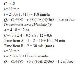
Example A storm
sewer is proposed to drain a 12 hectares drainage area shown in the figure
below. With given data in the table below determine the design discharge needed
to convey 5-year peak discharge.
Site : Area (ha) C Inlet time (min)
A : 4 0.8 10
B : 8 0.5 30
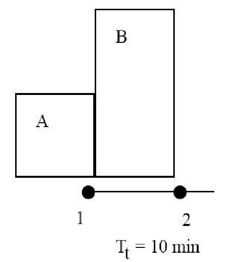
Solution
Upstream Area (Manhole 1): A = 4 ha
Related Topics