Chapter: Transmission Lines and Waveguides : High Frequency Transmission Lines
Transmission Line Equations a Radio Frequencies
TRANSMISSION LINE EQUATIONS A RADIO FREQUENCIES
There are two main forms of line at high frequency, namely
• Open wire line
• Coaxial line
• At Radio Frequency G may be considered zero
• Skin effect is considerable
• Due to skin effect L>>R
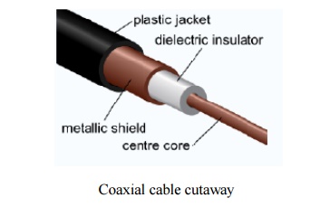
Coaxial cable is used as a transmission line for radio frequency signals, in applications such as connecting radio transmitters and receivers with their antennas, computer network (Internet) connections, and distributing cable television signals. One advantage of coax over other types of transmission line is that in an ideal coaxial cable the electromagnetic field carrying the signal exists only in the space between the inner and outer conductors. This allows coaxial cable runs to be installed next to metal objects such as gutters without the power losses that occur in other transmission lines, and provides protection of the signal from external electromagnetic interference.
Coaxial cable differs from other shielded cable used for carrying lower frequency signals such as audio signals, in that the dimensions of the cable are controlled to produce a repeatable and predictable conductor spacing needed to function efficiently as a radio frequency transmission line.
Like any electrical power cord, coaxial cable conducts AC electric current between locations. Like these other cables, it has two conductors, the central wire and the tubular shield. At any moment the current is traveling outward from the source in one of the conductors, and returning in the other. However, since it is alternating current, the current reverses direction many times a second. Coaxial cable differs from other cable because it is designed to carry radio frequency current. This has a frequency much higher than the 50 or 60 Hz used in mains (electric power) cables, reversing direction millions to billions of times per second. Like other types of radio transmission line, this requires special construction to prevent power losses:
If an ordinary wire is used to carry high frequency currents, the wire acts as an antenna, and the high frequency currents radiate off the wire as radio waves, causing power losses. To prevent this, in coaxial cable one of the conductors is formed into a tube and encloses the other conductor. This confines the radio waves from the central conductor to the space inside the tube. To prevent the outer conductor, or shield, from radiating, it is connected to electrical ground, keeping it at a constant potential.
The dimensions and spacing of the conductors must be uniform. Any abrupt change in the spacing of the two conductors along the cable tends to reflect radio frequency power back toward the source, causing a condition called standing waves. This acts as a bottleneck, reducing the amount of power reaching the destination end of the cable. To hold the shield at a uniform distance from the central conductor, the space between the two is filled with a semirigid plastic dielectric. Manufacturers specify a minimum bend radius[2] to prevent kinks that would cause reflections. The connectors used with coax are designed to hold the correct spacing through the body of the connector.
Each type of coaxial cable has a characteristic impedance depending on its dimensions and materials used, which is the ratio of the voltage to the current in the cable. In order to prevent reflections at the destination end of the cable from causing standing waves, any equipment the cable is attached to must present an impedance equal to the characteristic impedance (called 'matching'). Thus the equipment "appears" electrically similar to a continuation of the cable, preventing reflections. Common values of characteristic impedance for coaxial cable are 50 and 75 ohms.
Description
Coaxial cable design choices affect physical size, frequency performance, attenuation, power handling capabilities, flexibility, strength and cost. The inner conductor might be solid or stranded; stranded is more flexible. To get better high-frequency performance, the inner conductor may be silver plated. Sometimes copper-plated iron wire is used as an inner conductor.
The insulator surrounding the inner conductor may be solid plastic, a foam plastic, or may be air with spacers supporting the inner wire. The properties of dielectric control some electrical properties of the cable. A common choice is a solid polyethylene (PE) insulator, used in lower-loss cables. Solid Teflon (PTFE) is also used as an insulator. Some coaxial lines use air (or some other gas) and have spacers to keep the inner conductor from touching the shield. Many conventional coaxial cables use braided copper wire forming the shield. This allows the cable to be flexible, but it also means there are gaps in the shield layer, and the inner dimension of the shield varies slightly because the braid cannot be flat. Sometimes the braid is silver plated. For better shield performance, some cables have a double-layer shield. The shield might be just two braids, but it is more common now to have a thin foil shield covered by a wire braid. Some cables may invest in more than two shield layers, such as "quad-shield" which uses four alternating layers of foil and braid. Other shield designs sacrifice flexibility for better performance; some shields are a solid metal tube. Those cables cannot take sharp bends, as the shield will kink, causing losses in the cable. For high power radio-frequency transmission up to about 1 GHz coaxial cable with a solid copper outer conductor is available in sizes of 0.25 inch upwards. The outer conductor is rippled like a bellows to permit flexibility and the inner conductor is held in position by a plastic spiral to approximate an air dielectric.
Coaxial cables require an internal structure of an insulating (dielectric) material to maintain the spacing between the center conductor and shield. The dielectric losses increase in this order: Ideal dielectric (no loss), vacuum, air, Polytetrafluoroethylene (PTFE), polyethylene foam, and solid polyethylene. A low relative permittivity allows for higher frequency usage. An inhomogeneous dielectric needs to be compensated by a non-circular conductor to avoid current hot-spots.
Most cables have a solid dielectric; others have a foam dielectric which contains as much air as possible to reduce the losses. Foam coax will have about 15% less attenuation but can absorb moisture—especially at its many surfaces—in humid environments, increasing the loss. Stars or spokes are even better but more expensive. Still more expensive were the air spaced coaxials used for some inter-city communications in the middle 20th Century. The center conductor was suspended by polyethylene discs every few centimeters. In a miniature coaxial cable such as an RG-62 type, the inner conductor is supported by a spiral strand of polyethylene, so that an air space exists between most of the conductor and the inside of the jacket. The lower dielectric constant of air allows for a greater inner diameter at the same impedance and a greater outer diameter at the same cutoff frequency, lowering ohmic losses. Inner conductors are sometimes silver plated to smooth the surface and reduce losses due to skin effect. A rough surface prolongs the path for the current and concentrates the current at peaks and thus increases ohmic losses.
The insulating jacket can be made from many materials. A common choice is PVC, but some applications may require fire-resistant materials. Outdoor applications may require the jacket to resist ultraviolet light and oxidation. For internal chassis connections the insulating jacket may be omitted.
The ends of coaxial cables are usually made with RF connectors.
Open wire transmission lines have the property that the electromagnetic wave propagating down the line extends into the space surrounding the parallel wires. These lines have low loss, but also have undesirable characteristics. They cannot be bent, twisted or otherwise shaped without changing their characteristic impedance, causing reflection of the signal back toward the source. They also cannot be run along or attached to anything conductive, as the extended fields will induce currents in the nearby conductors causing unwanted radiation and detuning of the line. Coaxial lines solve this problem by confining the electromagnetic wave to the area inside the cable, between the center conductor and the shield. The transmission of energy in the line occurs totally through the dielectric inside the cable between the conductors. Coaxial lines can therefore be bent and moderately twisted without negative effects, and they can be strapped to conductive supports without inducing unwanted currents in them. In radio-frequency applications up to a few gigahertz, the wave propagates primarily in the transverse electric magnetic (TEM) mode, which means that the electric and magnetic fields are both perpendicular to the direction of propagation. However, above a certain cutoff frequency, transverse electric (TE) and/or transverse magnetic (TM) modes can also propagate, as they do in a waveguide. It is usually undesirable to transmit signals above the cutoff frequency, since it may cause multiple modes with different phase velocities to propagate, interfering with each other. The outer diameter is roughly inversely proportional to the cutoff frequency. A propagating surface-wave mode that does not involve or require the outer shield but only a single central conductor also exists in coax but this mode is effectively suppressed in coax of conventional geometry and common impedance. Electric field lines for this TM mode have a longitudinal component and require line lengths of a half-wavelength or longer.
Connectors
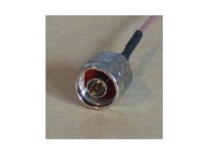
A coaxial connector (male N-type). Coaxial connectors are designed to maintain a coaxial form across the connection and have the same well-defined impedance as the attached cable. Connectors are often plated with high-conductivity metals such as silver or gold. Due to the skin effect, the RF signal is only carried by the plating and does not penetrate to the connector body. Although silver oxidizes quickly, the silver oxide that is produced is still conductive. While this may pose a cosmetic issue, it does not degrade performance.
Neper :
A neper (Symbol: Np) is a logarithmic unit of ratio. It is not an SI unit but is accepted for use alongside the SI. It is used to express ratios, such as gain and loss, and relative values. The name is derived from John Napier, the inventor of logarithms.
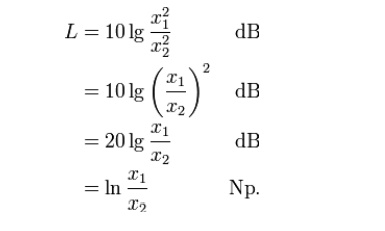
Like the decibel, it is a unit in a logarithmic scale, the difference being that where the decibel uses base-10 logarithms to compute ratios, the neper uses base e ≈ 2.71828. The value of a ratio in nepers, Np, is given by
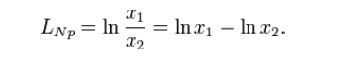
where x1 and x2 are the values of interest, and ln is the natural logarithm.
The neper is often used to express ratios of voltage and current amplitudes in electrical circuits (or pressure in acoustics), whereas the decibel is used to express power ratios. One kind of ratio may be converted into the other. Considering that wave power is proportional to the square of the amplitude, we have
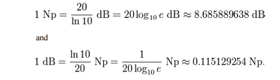
The decibel and the neper have a fixed ratio to each other. The (voltage) level is
Like the decibel, the neper is a dimensionless unit. The ITU recognizes both units.
Decibel
The decibel (dB) is a logarithmic unit of measurement that expresses the magnitude of a physical quantity (usually power or intensity) relative to a specified or implied reference level. Since it expresses a ratio of two quantities with the same unit, it is a dimensionless unit. A decibel is one tenth of a bel, a seldom-used unit.
The decibel is widely known as a measure of sound pressure level, but is also used for a wide variety of other measurements in science and engineering (particularly acoustics, electronics, and control theory) and other disciplines. It confers a number of advantages, such as the ability to conveniently represent very large or small numbers, a logarithmic scaling that roughly corresponds to the human perception of sound and light, and the ability to carry out multiplication of ratios by simple addition and subtraction.
The decibel symbol is often qualified with a suffix, which indicates which reference quantity or frequency weighting function has been used.
For example,
"dBm" indicates that the reference quantity is one milliwatt, while "dBu" is referenced to 0.775 volts RMS.[1]
The definitions of the decibel and bel use base-10 logarithms. For a similar unit using natural logarithms to base e, see neper.
Definitions
A decibel is one-tenth of a bel, i.e. 1 B=10 dB. The bel (B) is the logarithm of the ratio of two power quantities of 10:1, and for two field quantities in the ratio [8]. A field quantity is a quantity such as voltage, current, sound pressure, electric field strength, velocity and charge density, the square of which in linear systems is proportional to power. A power quantity is a power or a quantity directly proportional to power, e.g. energy density, acoustic intensity and luminous intensity. The calculation of the ratio in decibels varies depending on whether the quantity being measured is a power quantity or a field quantity.
Field quantities
When referring to measurements of field amplitude it is usual to consider the ratio of the squares of A1 (measured amplitude) and A0 (reference amplitude). This is because in most applications power is proportional to the square of amplitude, and it is desirable for the two decibel formulations to give the same result in such typical cases.
To calculate the ratio of 1 kW (one kilowatt, or 1000 watts) to 1 W in decibels, use the formula
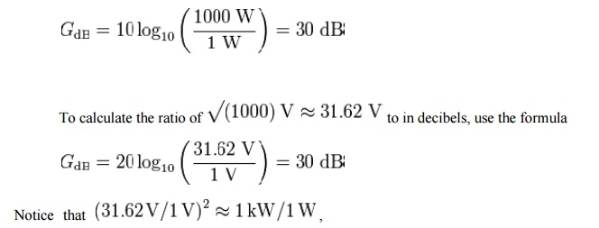
illustrating the consequence from the definitions above that GdB has the same value,30db , regardless of whether it is obtained with the 10-log or 20-log rules; provided that in the specific system being considered power ratios are equal to amplitude ratios squared.
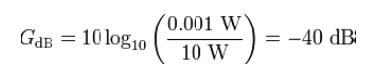
To calculate the ratio of 1 mW (one milliwatt) to 10 W in decibels, use the formula
To find the power ratio corresponding to a 3 dB change in level, use the formula
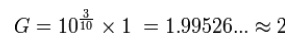
A change in power ratio by a factor of 10 is a 10 dB change. A change in power ratio by a factor of two is approximately a 3 dB change. More precisely, the factor is 103/10, or 1.9953, about 0.24% different from exactly 2. Similarly, an increase of 3 dB implies an increase in voltage by a factor of approximately , or about 1.41, an increase of 6 dB corresponds to approximately four times the power and twice the voltage, and so on. In exact terms the power ratio is 106/10, or about 3.9811, a relative error of about 0.5%.
Merits
The use of the decibel has a number of merits:
The decibel's logarithmic nature means that a very large range of ratios can be represented by a convenient number, in a similar manner to scientific notation. This allows one to clearly visualize huge changes of some quantity. (See Bode Plot and half logarithm graph.)
The mathematical properties of logarithms mean that the overall decibel gain of a multi-component system (such as consecutive amplifiers) can be calculated simply by summing the decibel gains of the individual components, rather than needing to multiply amplification factors. Essentially this is because log(A × B × C × ...) = log(A) + log(B) + log(C) + ...
The human perception of, for example, sound or light, is, roughly speaking, such that a doubling of actual intensity causes perceived intensity to always increase by the same amount, irrespective of the original level. The decibel's logarithmic scale, in which a doubling of power or intensity always causes an increase of approximately 3 dB, corresponds to this perception.
Absolute and relative decibel measurements
Although decibel measurements are always relative to a reference level, if the numerical value of that reference is explicitly and exactly stated, then the decibel measurement is called an "absolute" measurement, in the sense that the exact value of the measured quantity can be recovered using the formula given earlier. For example, since dBm indicates power measurement relative to 1 milliwatt,
• 0 dBm means no change from 1 mW. Thus, 0 dBm is the power level corresponding to a power of exactly 1 mW.
• 3 dBm means 3 dB greater than 0 dBm. Thus, 3 dBm is the power level corresponding to 103/10 × 1 mW, or approximately 2 mW. −6 dBm means 6 dB less than 0 dBm. Thus, −6 dBm is the power level corresponding to 10−6/10 × 1 mW, or approximately 250 µW (0.25 mW).
If the numerical value of the reference is not explicitly stated, as in the dB gain of an amplifier, then the decibel measurement is purely relative. The practice of attaching a suffix to the basic dB unit, forming compound units such as dBm, dBu, dBA, etc, is not permitted by SI.[10] However, outside of documents adhering to SI units, the practice is very common as illustrated by the following examples.
Related Topics