Chapter: Transmission Lines and Waveguides : High Frequency Transmission Lines
Important Short Questions and Answers: High Frequency and Radio Transmission Lines
RADIO FREQUENCY LINE
27.
State the assumptions for the analysis of the performance of the radio
frequency line.
1.Due to the skin effect ,the currents are
assumed to flow on the surface of the conductor. The internal inductance is
zero.
2.The resistance R increases with Ö f while
inductance L increases with f . Hence wL>>R.
3.The leakage conductance G is zero
28.State
the expressions for inductance L of a open wire line and coaxial line.
For open wire line ,
L=9.21*10-7(µ/µr +4ln d/a)=10-7(µr+9.21log d/a)
H/m
For coaxial line,
L = 4.60*10-7[log b/a]H/m
29.State
the expressions for the capacitance of a open wire line
For open wire line ,
C=(12.07)/(ln d/a)µµf/m
30.What
is dissipationless line?
A line for which the effect of resistance R is
completely neglected is called dissipationless line .
31.What
is the nature and value of Z0 for the dissipation less line?
For the dissipation less line, the Z0 is purley
resistive and given by,
Z0=R0 = Ö L/c
32.State
the values of a and b for the dissipation less line.
Answer:
a=0 and b=w ÖLC
33.What
are nodes and antinodes on a line?
The points along the line where magnitude of
voltage or current is zero are
called nodes while the the points along the
lines where magnitude of voltage or current first maximum are called antinodes
or loops.
34.What
is standing wave ratio?
The ratio of the maximum to minimum magnitudes
of voltage or current on a line having standing waves called standing waves
ratio.
½Emax½ ½Imin½ S = ¾¾ = ¾¾ ½Emin½ ½Imin½
35.What
is the range of values of standing wave ratio?
The range of values of standing wave ratio is
theoretically 1 to infinity.
36.State
the relation between standing wave ratio and reflection coefficient. Ans:
S = 1+½K½
¾¾¾
1-½K½
37.What
are standing waves?
If the transmission is not terminated in its
characteristic impedance ,then there
will be two waves traveling along the line
which gives rise to standing waves having fixed maxima and fixed minima.
38.What
is called standing wave ratio?
The ratio of the maximum to minimum magnitudes
of current or voltage on a line having standing wave is called the
standing-wave ratio S. That is,
S= E max = I max Emin
I min
39.State
the relation between standing were ratio S and reflection co-efficient k.
The relation between standing wave ratio S and
reflection co-efficient k is,
1+ k
S = 1- k S-1 Also k = S+1
40. How
will you make standing wave measurements on coaxial lines?
For coaxial lines it is necessary to use a
length of line in which a longitudinal slot, one half wavelength or more long
has been cut. A wire probe is inserted into the air dielectric of the line as a
pickup device, a vacuum tube voltmeter or other detector being connected
between probe and sheath as an indicator. If the meter provides linear
indications, S is readily determined. If the indicator is non linear,
corrections must be applied to the readings obtained.
41.Give
the input impedance of a dissipationless line.
The input impedance of a dissipationless line
is given by,
Z s = Es
= R0 1+ k < f -2bs I s 1- k <f -2bs
42.Give
the maximum and minimum input impedance of the dissipationless line.
Maximum input impedance, R max = R0 1+ k
1- k = SRo
Minimum input impedance, R min = Ro 1+ k
1- k = Ro
S
43.Give
the input impedance of open and short circuited lines.
The input impedance of open aned short
circuited lines are given by, Zsc = jRo tan 2 ps
l
44.Why
the point of voltage minimum is measured rather than voltage maximum?
The point of a voltage minimum is measured
rather than a voltage maximum because it is usually possible to determine the
exact point of minimum voltage with greater accuracy.
45. What
is the use of eighth wave line?
An eighth wave line is used to transform any
resistance to an impendence with a magnitude equal to Roof the line or to
obtain a magnitude match between a resistance of any value and a source of Ro
internal resistance.
46.
Give the input impendence of eighth wave line
terminated in a pure resistance Rr.
The input impendence of eighth wave line
terminated in a pure resistance Rr. Is given by
Zs = (ZR+jRo/Ro+jZR)
From the above equation it is seen that ½Zs½ =
Ro.
47.
Why is a quarter wave line called as impendence
inverter?
A quater wave line may be considered as an
impendence inverter because it can transform a low impendence in to ahigh
impendence and vice versa.
48. What
is the application of the quarter wave matching section ?
An important application of the quarter wave
matching sectionis to a couple a transmission line to a resistive load such as
an antenna .The quarter –wave matching section then must be designed to have a
characteristic impendence Ro so chosen that the antenna resistance Ra is
transformed to a value equal to the characteristic impendence Ra of the
transmission line.The characteristic impendence Ro of the matching section then
should be Ro’ = Ö Ra Ro
49. What
do you mean by copper insulators?
An application of the short circuited quarter
wave line is an insulator to support
an open wire line or the center conductor of a
coaxial line .This application makes se of the fact that the input impendence
of a quarter –wave shorted line is very high ,Such lines are sometimes referred
to as copper insulators.
50.
Bring out the significance of a half wavelength
line.
A half wavelength line may be considered as a
one- to – one transformer. It has its greatest utility in connecting load to a
source in cases where the load source cannot be made adjacent.
51.
Give some of the impendence –matching devices.
The quarter – wave line or transformer and the
tapered line are some of the impendence –matching devices.
52.
Explain impendence matching using stub.
In the method of impendence matching using stub
,an open or closed stub line of suitable length is used as a reactance shunted
across the transmission line at a designated distance from the load ,to tune
the length of the line and the load to resonance with an antiresonant
resistance equal to Ro.
53.Give
reasons for preferring a short- circuited stub when compared to an open –
circuited stub.
A short circuited stub is preferred to an open
circuited stub because of greater ease in constructions and because of the
inability to maintain high enough insulation resistance at the open –circuit
point to ensure that the stub is really opencircuited
.A shorted stub also has a lower loss of energy
due to radiation ,since the short – circuit can be definitely established with
a large metal plate ,effectively stopping all field propagation.
54.What
are the two independent measurements that must be made to find the location and
length of the stub.
The standing wave ratio S and the position of a
voltage minimum are the independent measurements that must be made to find the
location and length of the stub.
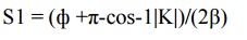
55.Give
the formula to calculate the distance of the point from the load at which the
stub is to be connected.
The formula to calculate the distance of the
point from the load at which the stub is to be connected is,
56.
Give the formula to calculate the distance d
from the voltage minimum to the point stub be connection.
The formula to calculate the distance d from
the voltage minimum to the point of stub be connection is,
d= cos-1|K| / (2β)
57.
Give the formula to calculate the length of the
short circuited stub.
The formula to calculate the length of the
short circuited stub is, 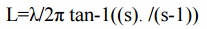
This is the length of the short – circuited
stub to be placed d meters towards the load from a point at which a voltage
minimum existed before attachment of the stub.
58. What
is the input impendence equation of a dissipation less line ?
The input impendence equation of a dissipation less line is given by (Zs/Ro)=(1+|K|(ϕ-2βs)/ (1-|K|(ϕ-2 βs)
59.Give
the equation for the radius of a circle diagram.
The equation for the radius of a circle diagram
is
R=(S2-1)/2S and
C = (S2+1)/2S
Where C is the shift of the center of the
circle on the positive Ra axis.
60.What
is the use of a circle diagram?
The circle diagram may be used to find the
input impendence of a line mof any chosen length.
61.
How is the circle diagram useful to find the
input impendence of short and open circuited lines?
An open circuited line has s = a ,the
correspondent circle appearing as the vertical axis .The input impendence is
then pure reactance , with the value for various electrical lengths determined
by the intersections of the corresponding bs circles with the vertical axis.
A short circuited line may be solved by
determining its amittance .The S circle is again the vertical axis, and susceptance
values may be read off at appropriate intersection of the bs circles with the
vertical axis.
62.
List the applications of the smith chart.
The applications of the smith chart are,
(i) It is used to find the input impendence and
input admittance of the line.
(ii)The smith chart may also be used for lossy
lines and the locus of points on a line then follows a spiral path towards the
chart center, due to attenuation.
(iii)
In
single stub matching
63. What
are the difficulties in single stub matching?
The difficulties of the smith chart are
(i) Single stub impedance matching requires the
stub to be located at a definite point on the line. This requirement frequently
calls for placement of the stub at an undesirable place from a mechanical view
point.
(ii)For a coaxial line, it is not possible to
determine the location of a voltage minimum without a slotted line section, so
that placement of a stub at the exact required point is difficult.
(iii)In the case of the single stub it was mentioned
that two adjustments were required ,these being location and length of the
stub.
64. What
is double stub matching?
Another possible method of impedance matching
is to use two stubs in which the locations of the stub are arbitrary,the two
stub lengths furnishing the required adjustments.The spacing is frequently made
_/4.This is called double stub matching.
65. Give
reason for an open line not frequently employed for impedance matching.
An open line is rarely used for impedance
matching because of radiation losses
from the open end,and capacitance effects and
the difficulty of a smooth adjustment of length.
66.
State the use of half wave line .
The expression for the input impendence of the
line is given by Zs = Zr
Thus the line repeats is terminating impedance
.Hence it is operated as one to one transformer .Its application is to connect
load to a source where they can not be made adjacent.
67.
Why Double stub matching is preferred over
single stub matching.
Double stub matching is preferred over single
stub due to following disadvantages of single stub.
1.Single stub matching is useful for a fixed
frequency . So as frequency changes the location of single stub will have to be
changed.
2.The single stub matching system is based on the
measurement of voltage minimum .Hence for coxial line it is very difficult to
get such voltage minimum, without using slotted line section.
Related Topics