Chapter: Transmission Lines and Waveguides : High Frequency Transmission Lines
Input Impedance of the Dissipation - Less Line & Open and Short Circuited Lines
INPUT IMPEDANCE OF THE DISSIPATION – LESS LINE & OPEN AND SHORT CIRCUITED LINES.
Input impedance of a transmission line:
Determine the input impedance of a transmission line of length L attached to a load (antenna) with impedance ZA. Consider the following circuit:
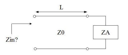
In low frequency circuit theory, the input impedance would simply be ZA. However, for high-frequency (or long) transmission lines, we know that the voltage and the current are given by:
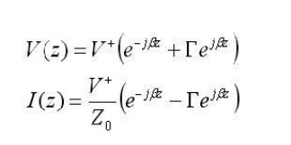
For simplicity, assume the transmission line is lossless, so that the propagation constant is purely imaginary. If we define z=0 to be at the terminals of the load or antenna, then we are interested in the ratio of the voltage to the current at location z=-L:
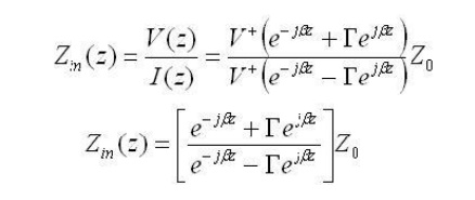
Using the definition for gamma (the voltage reflection coefficient), the above equation can be manipulated algebraically, and when evaluated at z=-L, we obtain:
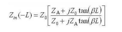
This last equation is fundamnetal to understanding transmission lines. The input impedance of a load ZA is transformed by a transmission line as in the above equation. This equation c an cause ZA to be transformed radically. An example will now be presented.
.Significance of impedance
The best coaxial able impedances in high-power, high-voltage, and low-attenuation applications were experimentally determined in 1929 at Bell Laboratories to be 30, 60, an d 77 Ω respectively. For an air dielectric coaxial cable with a diameter of 10 mm t he attenuation is lowest at 77 ohms when calculated for 10 GHz. The curve showing the power handling maxima at 30 ohms can be found here:
Consider the skin effect. The magnitude o f an alternating current in a conductor decays exponentially With distance beneath the surface, with the depth of penetration being proportional to the square root of the resistivity. This means t hat in a shield of finite thickness , some small amount of current will still be flowing on th e opposite surface of t he conductor. With a perfect conductor (i.e., zero resistivity ), all of the current would flow at t he surface, with no penetration into and through the conductor. Real cables have a shield ma de of an im perfect, although usually very good, conductor, so there will always be some leakage.
The gaps or holes, allow some of the electromagnetic field to penetrate to the other side. For example, braided shields have man y small gaps. The gaps are smaller when using a foil (solid metal) shield, but there is still a seam running the length o f the cable. Foil becomes increasingly rigid with increasing thickness, so a thin foil layer is often surrounded by a layer of braided metal, which offers greater flexibility for a given cross-section.
This type of leakage can also occur at locations o f poor contact between connectors at either end of the cab le.
Nodes and Anti nodes :
A t any point on the transmission line voltage or current value is zero called nodes. At any point on the line voltage or current value is maximum called Antinodes
Related Topics