Chapter: Transmission Lines and Waveguides : High Frequency Transmission Lines
Reflection Losses
REFLECTION LOSSES
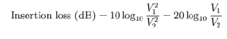
Insertion loss:
Insertion loss is a figure of merit for an electronic filter and this data is generally specified with a filter. Insertion loss is defined as a ratio of t he signal level in a test configuration without the filter installed (V1) to the signal level with the filter installed (V 2). This ratio is described in d B by the following equation:
Filters are sensitive to source and load impedances s o the exact performance of a filter in a circuit is difficult to precisely predict. Comparison s, however, of filter performance are possible if the insertion loss measurements are made with fixed source and load impedances, and 50 Ω is t he typical impedance to do this. This data is specified as com mon-mode or differential-mode. Common-m ode is a measure of the filter performance on signals that originate between the power lines and chassis ground, whereas differential-mode is a measure of the filter performance on signals that originate between the two power lines.
Link with Scattering parameters
Insertion Loss (I L) is defined as follows:
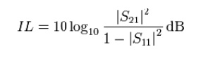
This definition results in a negative value for insertion loss, that is, it is really defining a gain, and a gain less than unity (i.e., a loss) will be negative when expressed in dBs. However, it is conventional to drop the minus sign so that an increasing loss is represented by an increasing positive number as would be intuitively expected
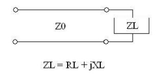
Reflection Coefficient: The characteristic impedance of a transmission line, and that the tx line gives rise to forward and backward travelling voltage and current waves. We will use this information to determine the voltage reflection coefficient, which relates the amplitude of the forward travelling wave to the amplitude of the backward travelling wave. To begin, consider the transmission line with characteristic impedance Z0 attached to a load with impedance ZL:
At the terminals where the transmission line is connected to the load, the overall voltage must be given by:
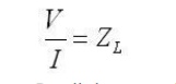
Recall the expressions for the voltage and current on the line (derived on the previous page):
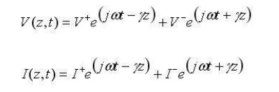
If we plug this into equation [1] (note that z is fixed, because we are evaluating this at a specific point, the end of the transmission line), we obtain:
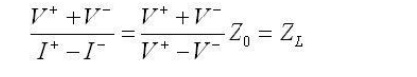
The ratio of the reflected voltage amplitude to that of the forward voltage amplitude is the voltage reflection coefficient. This can be solved for via the above equation:
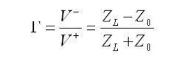
The reflection coefficient is usually denoted by the symbol gamma. Note that the magnitude of the reflection coefficient does not depend on the length of the line, only the load impedance and the impedance of the transmission line. Also, note that if ZL=Z0, then the line is "matched". In this case, there is no mismatch loss and all power is transferred to the load. At this point, you should begin to understand the importance of impedance matching: grossly mismatched impedances will lead to most of the power reflected away from the load.
Note that the reflection coefficient can be a real or a complex number.
Related Topics