Chapter: Mechanical : Strength of Materials : Torsion
Torsion
TORSION
Torsion
In solid mechanics, torsion is the twisting of an object due to an applied torque. In sections perpendicular to the torque axis, the resultant shear stress in this section is perpendicular to the radius.
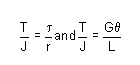
For solid shafts of uniform circular cross-section or hollow circular shafts with constant wall thickness, the torsion relations are:
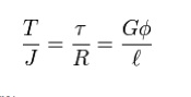
where:
· R is the outer radius of the shaft i.e. m, ft.
· t is the maximum shear stress at the outer surface.
· f is the angle of twist in radians.
· T is the torque (N·m or ft·lbf).
· l is the length of the object the torque is being applied to or over.
· G is the shear modulus or more commonly the modulus of rigidity and is usually given in gigapascals (GPa), lbf/in2 (psi), or lbf/ft2.
· J is the torsion constant for the section. It is identical to the polar moment of inertia for a round shaft or concentric tube only. For other shapes J must be determined by other means. For solid shafts the membrane analogy is useful, and for thin walled tubes of arbitrary shape the shear flow approximation is fairly good, if the section is not re-entrant. For thick walled tubes of arbitrary shape there is no simple solution, and finite element analysis (FEA) may be the best method.
· The product GJ is called the torsion.
Beam shear
Beam shear is defined as the internal shear stress of a beam caused by the sheer force applied to the beam.
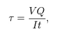
where
V = total shear force at the location in question;
Q = statical moment of area;
t = thickness in the material perpendicular to the shear;
I = Moment of Inertia of the entire cross sectional area.
This formula is also known as the Jourawski formula
Semi-monocoque shear
Shear stresses within a semi-monocoque structure may be calculated by idealizing the cross-section of the structure into a set of stringers (carrying only axial loads) and webs (carrying only shear flows). Dividing the shear flow by the thickness of a given portion of the semi-monocoque structure yields the shear stress. Thus, the maximum shear stress will occur either in the web of maximum shear flow or minimum thickness.
Also constructions in soil can fail due to shear; e.g., the weight of an earth-filled dam or dike may cause the subsoil to collapse, like a small and slide.
Impact shear
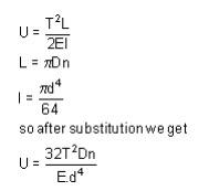
The maximum shear stress created in a solid round bar subject to impact is given as the equation:
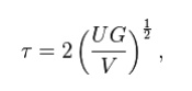
where
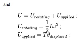
U = change in kinetic energy;
G = shear modulus;
V = volume of rod;
Bars of Solid and hollow circular section
The stiffness, k, of a body is a measure of the resistance offered by an elastic body to deformation. For an elastic body with a single Degree of Freedom (for example, stretching or compression of a rod), the stiffness is defined as

where
F is the force applied on the body
d is the displacement produced by the force along the same degree of freedom (for instance, the change in length of a stretched spring)
In the International System of Units, stiffness is typically measured in nektons per meter. In English Units, stiffness is typically measured in pound force (lbf) per inch.
Generally speaking, deflections (or motions) of an infinitesimal element (which is viewed as a point) in an elastic body can occur along multiple degrees of freedom (maximum of six DOF at a point). For example, a point on a horizontal beam can undergo both a vertical displacement and a rotation relative to its undeformed axis. When there are M degrees of freedom a M x M matrix must be used to describe the stiffness at the point. The diagonal terms in the matrix are the direct-related stiffnesses (or simply stiffnesses) along the same degree of freedom and the off-diagonal terms are the coupling stiffnesses between two different degrees of freedom (either at the same or different points) or the same degree of freedom at two different points. In industry, the term influence coefficient is sometimes used to refer to the coupling stiffness.
It is noted that for a body with multiple DOF, the equation above generally does not apply since the applied force generates not only the deflection along its own direction (or degree of freedom), but also those along other directions.
For a body with multiple DOF, in order to calculate a particular direct-related stiffness (the diagonal terms), the corresponding DOF is left free while the remaining should be constrained. Under such a condition, the above equation can be used to obtain the direct-related stiffness for the degree of freedom which is unconstrained. The ratios between the reaction forces (or moments) and the produced deflection are the coupling stiffnesses.
The inverse of stiffness is compliance, typically measured in units of metres per newton. In rheology it may be defined as the ratio of strain to stress and so take the units of reciprocal stress, e.g. 1/ Pa.
Stepped shaft ,Twist and torsion stiffness
–Compound shafts –Fixed and simply supported shafts
Shaft: The shafts are the machine elements which are used to transmit power in machines.
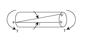
Twisting Moment: The twisting moment for any section along the bar / shaft is defined to be the algebraic sum of the moments of the applied couples that lie to one side of the section under consideration. The choice of the side in any case is of course arbitrary.
Shearing Strain: If a generator a ?? b is marked on the surface of the unloaded bar, then after the twisting moment 'T' has been applied this line moves to ab'. The angle ???'
measured in radians, between the final and original positions of the generators is defined as the shearing strain at the surface of the bar or shaft. The same definition will hold at any interior point of the bar.
Modulus of Elasticity in shear: The ratio of the shear stress to the shear strain is called the modulus of elasticity in shear OR Modulus of Rigidity and in represented by the symbol

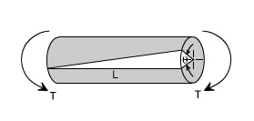
Angle of Twist: If a shaft of length L is subjected to a constant twisting moment T along its length, than the angle ? through which one end of the bar will twist relative to the other is known is the angle of twist.
Despite the differences in the forms of loading, we see that there are number of similarities between bending and torsion, including for example, a linear variation of stresses and strain with position.
In torsion the members are subjected to moments (couples) in planes normal to their axes.
For the purpose of desiging a circular shaft to withstand a given torque, we must develop an equation giving the relation between twisting moment, maximum shear stress produced, and a quantity representing the size and shape of the cross-sectional area of the shaft.
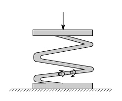
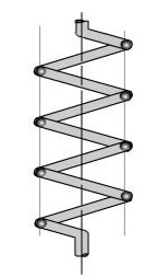
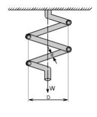
Not all torsion problems, involve rotating machinery, however, for example some types of vehicle suspension system employ torsional springs. Indeed, even coil springs are really curved members in torsion as shown in figure.
Many torque carrying engineering members are cylindrical in shape. Examples are drive shafts, bolts and screw drivers.
Simple Torsion Theory or Development of Torsion Formula : Here we are basically interested to derive an equation between the relevant parameters
Relationship in Torsion:
1 st Term: It refers to applied loading ad a property of section, which in the instance is the polar second moment of area.
2 nd Term: This refers to stress, and the stress increases as the distance from the axis increases.
3 rd Term: it refers to the deformation and contains the terms modulus of rigidity & combined term ( ??? l) which is equivalent to strain for the purpose of designing a circular shaft to with stand a given torque we must develop an equation giving the relation between Twisting moments max m shear stain produced and a quantity representing the size and shape of the cross ??sectional area of the shaft.
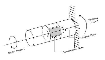
Refer to the figure shown above where a uniform circular shaft is subjected to a torque it can be shown that every section of the shaft is subjected to a state of pure shear, the moment of resistance developed by the shear stresses being every here equal to the magnitude, and opposite in sense, to the applied torque. For the purpose of deriving a simple theory to describe the behavior of shafts subjected to torque it is necessary make the following base assumptions.
Assumption:
(i) The materiel is homogenous i.e of uniform elastic properties exists throughout the material.
(ii) The material is elastic, follows Hook's law, with shear stress proportional to shear strain.
(iii) The stress does not exceed the elastic limit.
(iv) The circular section remains circular
(v)Cross section remain plane.
(vi) Cross section rotate as if rigid i.e. every diameter rotates through the same angle.
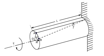
Consider now the solid circular shaft of radius R subjected to a torque T at one end, the other end being fixed Under the action of this torque a radial line at the free end of the shaft twists through an angle , point A moves to B, and AB subtends an angle ' at the fixed end. This is then the angle of distortion of the shaft i.e the shear strain.
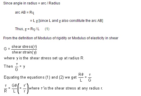
Since angle in radius = arc / Radius
arc AB = R?
= L ? [since L and ? also constitute the arc AB]
Thus, ? = R? / L (1)
From the definition of Modulus of rigidity or Modulus of elasticity in shear
Stresses: Let us consider a small strip of radius r and thickness dr which is subjected to shear stress t'.
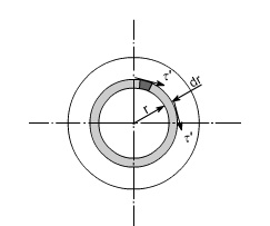
The force set up on each element
= stress x area
== 2 p t' . r2. dr
Since t' is a function of r, because it varies with radius so writing down t' in terms of r from the equation (1).
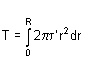
This force will produce a moment or torque about the center axis of the shaft.
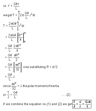
The total torque T on the section, will be the sum of all the contributions.
Since ?' is a function of r, because it varies with radius so writing down??' in terms of r from the equation (1).
Where
T = applied external Torque, which is constant over Length L;
J = Polar moment of Inertia

[ D = Outside diameter ; d = inside diameter ]
G = Modules of rigidity (or Modulus of elasticity in shear)
q = It is the angle of twist in radians on a length L.
Tensional Stiffness: The tensional stiffness k is defined as the torque per radius twist
i.e, k = T /q= GJ / L
Problem 1
A stepped solid circular shaft is built in at its ends and subjected to an externally applied torque. T0 at the shoulder as shown in the figure. Determine the angle of rotation ?0 of the shoulder section where T0 is applied ?
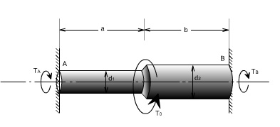
Solution: This is a statically indeterminate system because the shaft is built in at both ends. All that we can find from the statics is that the sum of two reactive torque TA and TB at the built ?? in ends of the shafts must be equal to the applied torque T0
Thus TA+ TB = T0 ------ (1)
[from static principles]
Where TA ,TB are the reactive torque at the built in ends A and B. wheeras T0 is the applied torque
From consideration of consistent deformation, we see that the angle of twist in each portion of the shaft must be same.
i.e qa = q b = q 0
using the relation for angle of twist
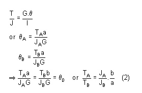
N.B: Assuming modulus of rigidity G to be same for the two portions
So the defines the ratio of TA and TB
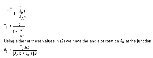
So by solving (1) & (2) we get
Non Uniform Torsion: The pure torsion refers to a torsion of a prismatic bar subjected to torques acting only at the ends. While the non uniform torsion differs from pure torsion in a sense that the bar / shaft need not to be prismatic and the applied torques may vary along the length.
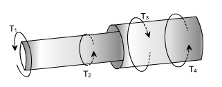
Here the shaft is made up of two different segments of different diameters and having torques applied at several cross sections. Each region of the bar between the applied loads between changes in cross section is in pure torsion, hence the formula's derived earlier may be applied. Then form the internal torque, maximum shear stress and angle of rotation for each region can be calculated from the relation
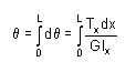
The total angle to twist of one end of the bar with respect to the other is obtained by summation using the formula
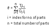
If either the torque or the cross section changes continuously along the axis of the bar, then the ? (summation can be replaced by an integral sign ( ? ). i.e We will have to consider a differential element.
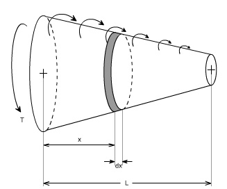
After considering the differential element, we can write

Substituting the expressions for Tx and Jx at a distance x from the end of the bar, and then integrating between the limits 0 to L, find the value of angle of twist may be determined.
Application to close-coiled helical springs
Closed Coiled helical springs subjected to axial loads:
Definition: A spring may be defined as an elastic member whose primary function is to deflect or distor under the action of applied load; it recovers its original shape when load is released.
or
Springs are energy absorbing units whose function is to store energy and to restore it slowly or rapidl depending on the particular application.
Important types of springs are:
There are various types of springs such as
(i) helical spring: They are made of wire coiled into a helical form, the load being applied along the axi of the helix. In these type of springs the major stresses is torsional shear stress due to twisting. They are both used in tension and compression.
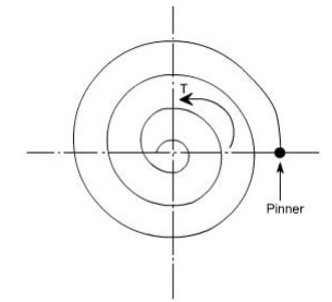
(ii) Spiral springs: They are made of flat strip of metal wound in the form of spiral and loaded in torsion.
In this the major stresses are tensile and compression due to bending.
(iv) Leaf springs: They are composed of flat bars of varying lengths clamped together so as to obtai greater efficiency . Leaf springs may be full elliptic, semi elliptic or cantilever types, In these type o springs the major stresses which come into picture are tensile & compressive.
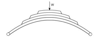
These type of springs are used in the automobile suspension system.
Uses of springs :
(a)To apply forces and to control motions as in brakes and clutches.
(b) To measure forces as in spring balance.
(c) To store energy as in clock springs.
(d) To reduce the effect of shock or impact loading as in carriage springs.
(e) To change the vibrating characteristics of a member as inflexible mounting of motors.
Derivation of the Formula :
In order to derive a necessary formula which governs the behaviour of springs, consider a closed coile spring subjected to an axial load W.
Let
W = axial load
D = mean coil diameter
d = diameter of spring wire n = number of active coils
C = spring index = D / d For circular wires l = length of spring wire
G = modulus of rigidity x = deflection of spring q = Angle of twist
when the spring is being subjected to an axial load to the wire of the spring gets be twisted like a shaft.
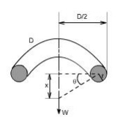
If q is the total angle of twist along the wire and x is the deflection of spring under the action of load W along the axis of the coil, so that
x = D / 2 .
again l = D n [ consider ,one half turn of a close coiled helical spring ]
Maximum shear stress in spring section including Wahl Factor
Wahl's factor
Assumptions: (1) The Bending & shear effects may be neglected
(2) For the purpose of derivation of formula, the helix angle is considered to be so small that it may be neglected.
Any one coil of a such a spring will be assumed to lie in a plane which is nearly r to the axis of the spring. This requires that adjoining coils be close together. With this limitation, a section taken perpendicular to the axis the spring rod becomes nearly vertical. Hence to maintain equilibrium of a segment of the spring, only a shearing force V = F and Torque T = F. r are required at any X –section. In the analysis of springs it is customary to assume that the shearing stresses caused by the direct shear force is uniformly distributed and is negligible
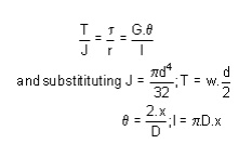
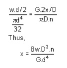
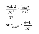
so applying the torsion formula.
Using the torsion formula i.e
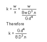
SPRING DEFLECTION
Spring striffness: The stiffness is defined as the load per unit deflection therefore
Shear stress
WAHL'S FACTOR :
In order to take into account the effect of direct shear and change in coil curvature a stress factor is defined, which is known as Wahl's factor
K = Wahl' s factor and is defined as
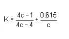
Where C = spring index
= D/d
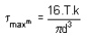
if we take into account the Wahl's factor than the formula for the shear stress becomes
Strain Energy : The strain energy is defined as the energy which is stored within a material when the work has been done on the material.
In the case of a spring the strain energy would be due to bending and the strain energy due to bending is given by the expansion
Deflection of helical coil springs under axial loads
Deflection of springs
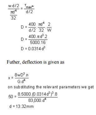
Example: A close coiled helical spring is to carry a load of 5000N with a deflection of 50 mm and a maximum shearing stress of 400 N/mm2 .if the number of active turns or active coils is 8.Estimate the following:
(i) wire diameter
(ii) mean coil diameter
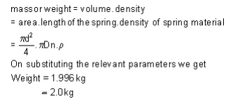
(iii) weight of the spring.
Assume G = 83,000 N/mm2 ; = 7700 kg/m3
solution :
(i) for wire diametre if W is the axial load, then
Therefore,
D = .0314 x (13.317)3mm =74.15mm
D = 74.15 mm
Weight
Design of helical coil springs
Helical spring design
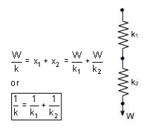
Springs in Series: If two springs of different stiffness are joined endon and carry a common load W, they are said to be connected in series and the combined stiffness and deflection are given by the following equation.
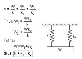
Springs in parallel: If the two spring are joined in such a way that they have a common deflection ‘x' ; then they are said t shared between the two springs and total load W = W1 + W2
stresses in helical coil springs under torsion loads
Stresses under torsion
Shear Stress in the Shaft
When a shaft is subjected to a torque or twisting, a shearing stress is produced in the shaft. The shear stress varies from zero in the axis to a maximum at the outside surface of the shaft.
The shear stress in a solid circular shaft in a given position can be expressed as:
s = T r / Ip (1)
where
s = shear stress (MPa, psi)
T = twisting moment (Nmm, in lb)
r = distance from center to stressed surface in the given position (mm, in)
Ip = "polar moment of inertia" of cross section (mm4, in4)
The "polar moment of inertia" is a measure of an object's ability to resist torsion.
Circular Shaft and Maximum Moment
Maximum moment in a circular shaft can be expressed as:
Tmax = smax Ip / R (2)
Where
Tmax = maximum twisting moment (Nmm, in lb)
smax = maximum shear stress (MPa, psi)
R = radius of shaft (mm, in)
Combining (2) and (3) for a solid shaft
Tmax = (p/16) smax D3 (2b)
Combining (2) and (3b) for a hollow shaft
Tmax = (p/16) smax (D4 - d4) / D (2c)
Circular Shaft and Polar Moment of Inertia
Polar moment of inertia of a circular solid shaft can be expressed as
Ip = p R4/2 = p D4/32 (3)
D = shaft outside diameter (mm, in)
Polar moment of inertia of a circular hollow shaft can be expressed as
Ip = p (D4 - d4) /32 (3b)
where
d = shaft inside diameter (mm, in)
Diameter of a Solid Shaft
Diameter of a solid shaft can calculated by the formula
D = 1.72 (Tmax/smax)1/3 (4)
Torsional Deflection of Shaft
The angular deflection of a torsion shaft can be expressed as
? = L T / Ip G (5)
where
? = angular shaft deflection (radians) L = length of shaft (mm, in)
G = modulus of rigidity (Mpa, psi)
The angular deflection of a torsion solid shaft can be expressed as
? = 32 L T / (G p D4) (5a)
The angular deflection of a torsion hollow shaft can be expressed as
? = 32 L T / (G p (D4- d4)) (5b)
The angle in degrees can be achieved by multiplying the angle ? in radians with 180/p Solid shaft (p replaced)
?degrees ˜584 L T / (G D4) (6a)
Hollow shaft (p replaced)
?degrees ˜584 L T / (G (D4- d4) (6b)
Related Topics