Chapter: Mechanical and Electrical : Power Plant Engineering : Power From Renewable Energy
Thermo Electric conversion system
Thermo Electric conversion system
Thermo electric Conversion System:
The quest for a reliable, silent, energy converted with no
moving parts that transforms heat to electrical power has led engineers to
reconsider a set of phenomena called the Thermoelectric effects. These effects,
known for over a hundred years, have permitted the development of small, self
contained electrical power sources.
Seebeck (thermoelectric) effect:
The
German Scientist Seebeck (in 1822) discovered that if two dissimilar material
are joined to form a loop and the two junctions maintained at different
temperatures, and e.m.f will be set up around the loop. The magnitude of e.m.f.
will be E = aDT where DT is the temperature difference
between the two junctions and ais the Seebeck co-efficient. This
effect has long been used in thermocouples to measure temperatures.
Thermoelectric Power Generator:
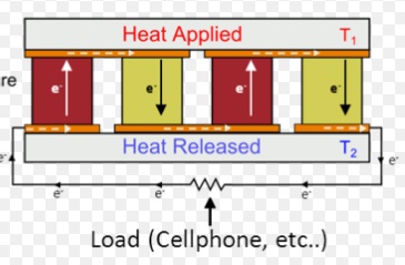
Figure
shows a schematic diagram of a thermoelectric power generator. The thermocouple
materials A and B are joined at the hot end, but the other ends are kept cold;
an electric voltage or electromotive force is then generated between the cold
ends. A.D.C (Direct Current) will flow in a circuit or load connected between
these ends. The flow of current will continue as long as the heat
is
supplied to the hot junction and removed from the cold ends. For a given
thermocouple, the voltage and electric power output are increased by increasing
the temperature difference between the hot and cold ends.
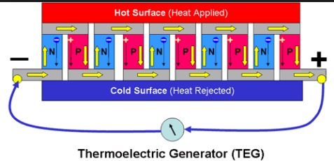
In
a practical thermoelectric converter, several thermocouples are convected in
series to increases both voltage and power as shown in figure. If the output
voltage is insufficient to operate a particular device or equipment, it can be
increased, with little loss of power, by an inverted transformers combination.
The direct current generated by the thermocouples is first changed into
alternating current of essentially the same average by means of an inverter. The
alternating current and voltage in then increased to the desired value with the
help of a transformer. The high voltage alternating current can be reconverted
into direct current if required, by the use of a rectifier.
The source of heat for a thermoelectric generator may be
small oil or gas burner, a radio- isotope or direct solar radiation.

Figure: Thermoelectric generator.

Figure:
Thermocouples in series (to increase voltage).
A
typical couple operating with hot and cold junction temperatures of 600°C and 200°C could
be designed to give about 0.1 V and 2 A i.e., about 0.5 W, so that a 1 kW
device could require about 5000 couples in series.
Taking
into account mechanical characteristics, stability under operating conditions
and ease of fabrication, Bismuth telluride appears to be most suitable
material. It can be alloyed with such materials as Bismuth selenide, Antimony
telluride, Lead selenide and Tin telluride to give improved properties.
Research
is being carried out on the possibility of using thermoelectric devices within
the core of a nuclear reactor. The hot junction would be located on the fuel
element and the cold junctions in contact with the coolants.
Related Topics