Chapter: Fundamentals of Database Systems : Object, Object-Relational, and XML: Concepts, Models, Languages, and Standards : Object and Object-Relational Databases
The ODMG Object Model and the Object Definition Language ODL
The ODMG Object Model and the Object Definition Language ODL
As we discussed in the introduction to Chapter 4, one of the reasons for
the success of commercial relational DBMSs is the SQL standard. The lack of a
standard for ODMSs for several years may have caused some potential users to
shy away from converting to this new technology. Subsequently, a consortium of
ODMS vendors and users, called ODMG (Object Data Management Group), proposed a
standard that is known as the ODMG-93 or ODMG 1.0 standard. This was revised
into ODMG 2.0, and later to ODMG 3.0. The standard is made up of several parts,
including the object model, the object definition language (ODL), the object query language (OQL), and the bindings to object-oriented programming languages.
In this section, we describe the ODMG object model and the ODL. In
Section 11.4, we discuss how to design an ODB from an EER conceptual schema. We
will give an overview of OQL in Section 11.5, and the C++ language binding in
Section 11.6. Examples of how to use ODL, OQL, and the C++ language binding
will use the UNIVERSITY
database example introduced in Chapter 8. In our
description, we will follow the ODMG 3.0 object model
as described in Cattell et al. (2000). It is important to note that many of the ideas embodied in the ODMG
object model are based on two decades of research into conceptual modeling and
object databases by many researchers.
The incorporation of object concepts into the SQL relational database
standard, leading to object-relational technology, was presented in Section
11.2.
1. Overview of the
Object Model of ODMG
The ODMG object model is the data model
upon which the object definition language (ODL) and object query language (OQL)
are based. It is meant to provide a standard data model for object databases,
just as SQL describes a standard data model for relational databases. It also
provides a standard terminology in a field where the same terms were sometimes
used to describe different concepts. We will try to adhere to the ODMG
terminology in this chapter. Many of the concepts in the ODMG model have
already been discussed in Section 11.1, and we assume the reader has read this
section. We will point out whenever the ODMG terminology differs from that used
in Section 11.1.
Objects and Literals. Objects
and literals are the basic building blocks of the object
model. The main difference between the two is that an object has both an object
identifier and a state (or current
value), whereas a literal has a value (state) but no object identifier.22 In either case, the value can
have a complex structure. The object state can change over time by modifying
the object value. A literal is basically a constant value, possibly having a
complex structure, but it does not change.
An object has five aspects: identifier,
name, lifetime, structure, and creation.
The object
identifier is a unique system-wide identifier (or Object_id).23 Every object must
have an object identifier.
Some objects may optionally be given a unique name within a particular
ODMS—this
name can be used to locate the object, and the system should return the object
given that name. Obviously, not all individual objects will have unique names.
Typically, a few objects, mainly those that hold collections of objects of a
particular object type—such as extents—will
have a name. These names are used as entry
points to the database; that is, by locating these objects by their unique
name, the user can then locate other objects that are referenced from these
objects. Other important objects in the application may also have unique names,
and it is possible to give more than one name to an object. All names
within a particular ODMS must be unique.
The lifetime
of an object specifies whether it is a persistent
object (that is, a database object) or transient
object (that is, an object in an executing pro-gram that disappears after
the program terminates). Lifetimes are independent of types—that is, some
objects of a particular type may be transient whereas others may be persistent.
The structure
of an object specifies how the object is constructed by using the type
constructors. The structure specifies whether an object is atomic or not. An atomic
object refers to a single object that follows a user-defined type, such as Employee or Department. If an object is not atomic,
then it will be
composed
of other objects. For example, a collection
object is not an atomic object, since its state will be a collection of
other objects.25 The term atomic
object is different from how we
defined the atom constructor in
Section 11.1.3, which referred to all
values of built-in data types. In the ODMG model, an atomic object is any individual user-defined object. All
values of the basic built-in data types are considered to be literals.
Object creation
refers to the manner in which an object can be created. This is typically
accomplished via an operation new for
a special Object_Factory
interface. We shall describe this in more detail later in this section.
In the
object model, a literal is a value
that does not have an object
identifier. However, the value may have a simple or complex structure. There
are three types of literals: atomic, structured, and collection.
Atomic
literals26 correspond
to the values of basic data types and are predefined. The basic data types of
the object model include long, short, and unsigned integer numbers (these are
specified by the keywords long, short, unsigned long, and
unsigned short in ODL), regular and double precision floating point numbers (float, double), Boolean values (boolean), single
characters (char),
character strings (string), and
enumeration types (enum), among
others.
Structured
literals correspond roughly to values that are constructed using the tuple constructor described in
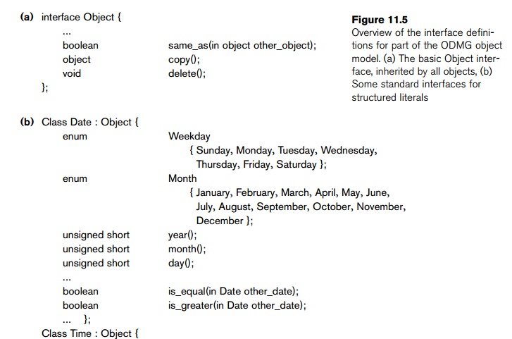
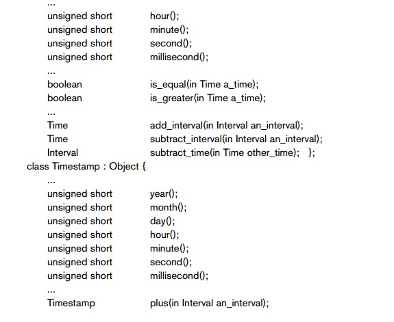
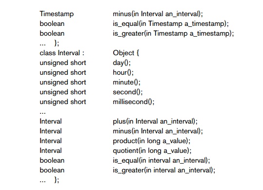
Section 11.1.3. The built-in structured lit-erals include Date, Interval, Time, and Timestamp (see Figure 11.5(b)).
Additional
user-defined structured literals can be defined as needed by each application.27
User-defined structures are created using the STRUCT key-word in ODL, as in the C and C++ programming languages.
Collection
literals specify a literal value that is a collection of objects or val-ues but
the collection itself does not have an Object_id. The
collections in the object model can be defined by the type generators set<T>, bag<T>, list<T>, and array<T>, where T is the type of objects or values in the collection.28
Another collection type is dictionary<K, V>, which is a collection of
associations <K, V>, where
each K is a key (a unique search
value) associated with a value V;
this can be used to create an index on a collection of values V.
Figure
11.5 gives a simplified view of the basic types and type generators of the
object model. The notation of ODMG uses three concepts: interface, literal, and class.
Following the ODMG terminology, we use the word behavior to refer to operations
and state to refer to properties (attributes and
relationships). An interface
specifies only behavior of an object type and is typically noninstantiable (that is, no objects are created corresponding to
an interface). Although an interface may have state properties (attributes and
relationships) as part of its specifications, these cannot be inherited from the interface. Hence, an interface serves
to define operations that can be inherited
by other interfaces, as well as by classes that define the user-defined objects
for a particular application. A class
specifies both state (attributes) and behavior (operations) of an object type,
and is instantiable. Hence, database
and application objects are typically created based on the user-specified class
declarations that form a database schema. Finally, a literal declaration specifies state but no behavior. Thus, a
literal instance holds a simple or complex structured value but has neither an
object identifier nor encapsulated operations.
Figure
11.5 is a simplified version of the object model. For the full specifications,
see Cattell et al. (2000). We will describe some of the constructs shown in
Figure 11.5 as we describe the object model. In the object model, all objects
inherit the basic inter-face operations of Object, shown
in Figure 11.5(a); these include operations such as copy (creates a new copy of the
object), delete (deletes the object), and same_as (compares the object’s identity
to another object).29 In general, operations are applied to objects
using the dot notation. For example,
given an object O, to com-pare it
with another object P, we write
O.same_as(P)
The
result returned by this operation is Boolean and would be true if the identity
of P is the same as that of O, and false otherwise. Similarly, to
create a copy P of object O, we write
P = O.copy()
An
alternative to the dot notation is the arrow
notation: O–>same_as(P) or
O–>copy().
2. Inheritance in the
Object Model of ODMG
In the
ODMG object model, two types of inheritance relationships exist: behavior-only
inheritance and state plus behavior inheritance. Behavior inheritance is also known as ISA or interface inheritance,
and is specified by the colon (:) notation.30 Hence, in the ODMG
object model, behavior inheritance requires the supertype to be an interface,
whereas the subtype could be either a class or another interface.
The other
inheritance relationship, called EXTENDS inheritance, is specified by the
keyword extends. It is used to inherit both
state and behavior strictly among classes, so both the supertype and the
subtype must be classes. Multiple inheritance via extends is not permitted. However,
multiple inheritance is allowed for behavior
inheritance
via the colon (:) notation. Hence, an interface may inherit behavior from
several other interfaces. A class may also inherit behavior from several
inter-faces via colon (:) notation, in addition to inheriting behavior and state
from at most one other class via extends. In Section 11.3.4 we will give
examples of how these two inheritance
relationships—“:” and extends—may be
used.
3. Built-in Interfaces
and Classes in the Object Model
Figure
11.5 shows the built-in interfaces and classes of the object model. All
inter-faces, such as Collection, Date, and Time, inherit the basic Object interface. In the object model,
there is a distinction between collection objects, whose state contains
multiple objects or literals, versus atomic (and structured) objects, whose
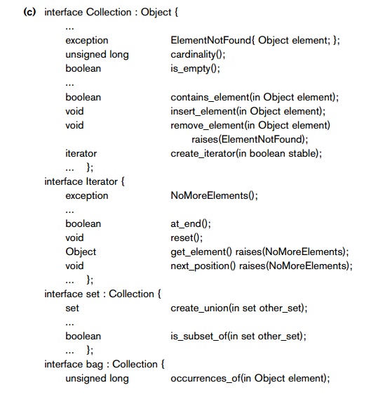
state is an individual object or literal. Collection
objects inherit the basic Collection
interface shown in Figure 11.5(c), which shows the operations for all
collection objects. Given a collection object O, the O.cardinality() operation returns the number
of elements in the collection. The operation O.is_empty()
returns true if the collection O is
empty, and returns false otherwise. The operations O.insert_element(E) and O.remove_element(E) insert or remove an element E from the collection O. Finally, the operation O.contains_element(E) returns true if the collection O includes element E,
and returns false otherwise. The operation I
= O.create_iterator()
creates an iterator object I
for the collection object O, which can iterate over each element
in the collection. The interface for
iterator objects is also shown in Figure 11.5(c). The I.reset()
operation sets the iterator at the first element in a collection (for an unordered collection, this would be
some arbitrary element), and I.next_position() sets the iterator to the next
element. The I.get_element() retrieves the current ele-ment, which is the element
at which the iterator is currently positioned.
The ODMG
object model uses exceptions for
reporting errors or particular conditions. For example, the ElementNotFound exception in the Collection interface would be raised by the
O.remove_element(E) operation if E is not an element in the collec-tion O. The NoMoreElements
exception in the iterator interface would be raised by the I.next_position()
operation if the iterator is currently positioned at the last ele-ment in the
collection, and hence no more elements exist for the iterator to point to.
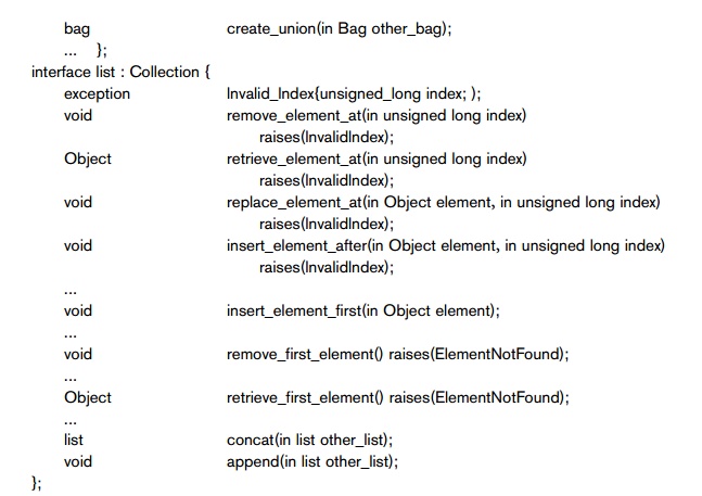
Collection objects are further specialized
into set, list, bag, array, and dictionary, which inherit the operations of the Collection interface. A set<T> type generator can be used to create objects such that the
value of object O is a set whose elements are of type T. The Set interface includes the additional
operation P = O.create_union(S) (see Figure 11.5(c)), which returns a new object P of type set<T> that is the union of the two sets O and S. Other operations similar to create_union (not
shown in Figure 11.5(c)) are create_intersection(S) and create_difference(S).
Operations for set comparison include the O.is_subset_of(S) operation, which returns true if the set object O is a subset of some other set object S, and returns false otherwise. Similar
operations (not shown in Figure 11.5(c)) are is_proper_subset_of(S), is_superset_of(S), and is_proper_superset_of(S). The bag<T> type generator
allows duplicate elements in the
collection and also inherits the Collection
interface. It has three operations— create_union(b), create_intersection(b), and create_difference(b)—that all
return a new object of
type bag<T>. A list<T> object type inherits the Collection operations and can be used to
create col-lections where the order of the elements is important. The value of
each such object O is an ordered list whose elements are of type T. Hence,
we can refer to the first, last, and ith element in the list. Also, when we
add an element to the list, we must specify the position in the list where the
element is inserted. Some of the list
operations are shown in Figure 11.5(c). If O
is an object of type list<T>, the operation O.insert_element_first(E) inserts the element E before the first element in the list O, so that E becomes the first
element in the list. A similar operation (not shown) is O.insert_element_last(E). The operation O.insert_element_after(E,
I) in Figure 11.5(c) inserts the
element E after the ith element in the list O and will raise the exception InvalidIndex if no ith
element exists in O. A similar operation (not shown)
is O.insert_element_before(E,
I). To remove elements from the list, the operations are E = O.remove_first_element(), E = O.remove_last_element(), and E = O.remove_element _at(I); these operations remove
the indicated element from the list
and return the element as the operation’s
result. Other operations retrieve an element without removing it from the list.
These are E = O.retrieve_first_element(), E = O.retrieve _last_element(), and
E = O.retrieve_element_at(I). Also, two operations to manipulate lists are defined. They are P = O.concat(I), which creates a new list P
that is the concatenation of lists O
and I (the elements in list O followed by those in list I), and O.append(I), which appends the elements of list I to the end of list O (without creating a new list
object).
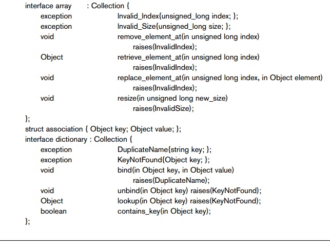
The array<T> object type also inherits the Collection operations, and is similar to list. Specific
operations for an array object O are O.replace_element_at(I, E),
which replaces the array element at position I with element E; E = O.remove_element_at(I), which retrieves the ith
element and replaces it with a NULL value;
and E = O.retrieve_element_at(I), which simply retrieves the ith element of the array. Any of these operations can raise the
exception InvalidIndex if I is greater than the array’s size. The
operation O.resize(N) changes the number of array elements to N.
The last
type of collection objects are of type dictionary<K,V>.
This allows the creation of a collection of association pairs <K,V>,
where all K (key) values are unique.
This allows for associative retrieval of a particular pair given its key value
(similar to an index). If O is a
collection object of type dictionary<K,V>,
then O.bind(K,V) binds value V to the
key K as an association <K,V>
in the collection, whereas O.unbind(K) removes the association with key K from O, and V = O.lookup(K) returns the value V associated
with key K in O. The latter two operations can raise the exception KeyNotFound.
Finally, O.contains_key(K) returns true if key
K exists in O, and
returns false otherwise.
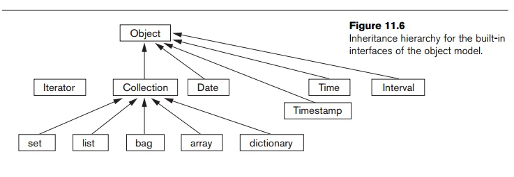
Figure
11.6 is a diagram that illustrates the inheritance hierarchy of the built-in
con-structs of the object model. Operations are inherited from the supertype to
the sub-type. The collection interfaces described above are not directly instantiable; that is, one
cannot directly create objects based on these interfaces. Rather, the
interfaces can be used to generate user-defined collection types—of type set, bag, list, array, or dictionary—for a particular database
application. If an attribute or class has a collection type, say a set, then it will inherit the
operations of the set
interface. For exam-ple, in a UNIVERSITY database
application, the user can specify a type for set<STUDENT>,
whose state would be sets of STUDENT objects.
The programmer can then
use the operations for set<T> to manipulate an instance of type set<STUDENT>. Creating application
classes is typically done by utilizing the object definition
language ODL (see Section 11.3.6).
It is
important to note that all objects in a particular collection must be of the same type. Hence, although the keyword any appears in the specifications of
collection interfaces in Figure
11.5(c), this does not mean that objects of any type can be inter-mixed within
the same collection. Rather, it means that any type can be used when specifying
the type of elements for a particular collection (including other collec-tion
types!).
4. Atomic (User-Defined) Objects
The
previous section described the built-in collection types of the object model.
Now we discuss how object types for atomic
objects can be constructed. These are specified using the keyword class in ODL. In the object model, any
user-defined object that is not a collection object is called an atomic object.
For
example, in a UNIVERSITY database
application, the user can specify an object type (class) for STUDENT objects. Most such objects will
be structured objects; for example,
a STUDENT object will have a complex
structure, with many attributes, relationships, and operations, but it is still
considered atomic because it is not a collection. Such a user-defined atomic
object type is defined as a class by specifying its properties and operations.
The properties define the state of the object and are further distinguished
into attributes and relationships. In this subsection, we
elabo-rate on the three types of components—attributes, relationships, and
operations—that a user-defined object type for atomic (structured) objects can
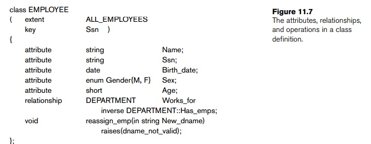
include. We illustrate our discussion with the two classes EMPLOYEE and DEPARTMENT shown in Figure 11.7.
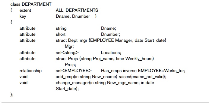
An attribute is a property that describes some aspect of an object. Attributes have values (which are typically literals having a simple or complex structure) that are stored within the object. However, attribute values can also be Object_ids of other objects. Attribute values can even be specified via methods that are used to calculate the attribute value. In Figure 11.7 the attributes for EMPLOYEE are Name, Ssn, Birth_date, Sex, and Age, and those for DEPARTMENT are Dname, Dnumber, Mgr, Locations, and Projs. The Mgr and Projs attributes of DEPARTMENT have complex structure and are defined via struct, which corresponds to the tuple constructor of Section 11.1.3. Hence, the value of Mgr in each DEPARTMENT object will have two components: Manager, whose value is an Object_id that references the EMPLOYEE object that manages the DEPARTMENT, and Start_date, whose value is a date. The locations attribute of DEPARTMENT is defined via the set constructor, since each DEPARTMENT object can have a set of locations.
A relationship is a property that specifies
that two objects in the database are related. In the object model of ODMG, only
binary relationships (see Section 7.4) are explicitly represented, and each
binary relationship is represented by a pair
of inverse references specified
via the keyword relationship. In Figure 11.7, one relationship exists that relates each EMPLOYEE to the DEPARTMENT in which he or she works— the Works_for relationship of EMPLOYEE. In the inverse direction, each DEPARTMENT is related to the set of EMPLOYEES that work in the DEPARTMENT— the Has_emps relationship of DEPARTMENT. The keyword inverse specifies that these two
properties define a single conceptual relationship in inverse directions.
By
specifying inverses, the database system can maintain the referential integrity
of the relationship automatically. That is, if the value of Works_for for a particular EMPLOYEE E refers to DEPARTMENT D, then the value of Has_emps for DEPARTMENT
D must
include a reference to E
in its
set of EMPLOYEE references. If the database designer desires to
have a relationship to be represented in only
one direction, then it has to be
modeled as an attribute (or operation). An example is the Manager component
of the Mgr attribute in DEPARTMENT.
In
addition to attributes and relationships, the designer can include operations in object type (class)
specifications. Each object type can have a number of operation signatures,
which specify the operation name, its argument types, and its returned value, if applicable. Operation names
are unique within each object type, but they can be overloaded by having the
same operation name appear in distinct object types. The operation signature
can also specify the names of exceptions
that can occur during operation execution. The implementation of the operation
will include the code to raise these exceptions. In Figure 11.7 the EMPLOYEE class has one operation: reassign_emp, and the DEPARTMENT class has two operations: add_emp and change_manager.
5. Extents, Keys, and
Factory Objects
In the
ODMG object model, the database designer can declare an extent (using the keyword extent) for any
object type that is defined via a class
declaration. The extent is given
a name, and it will contain all persistent objects of that class. Hence, the extent behaves as a set
object that
holds all persistent objects of the class. In Figure 11.7 the EMPLOYEE and DEPARTMENT classes have extents called ALL_EMPLOYEES and ALL_DEPARTMENTS, respectively. This is similar
to creating two objects—one of type set<EMPLOYEE> and the second of type set<DEPARTMENT>—and making them persistent
by naming them ALL_EMPLOYEES and ALL_DEPARTMENTS. Extents are also used to
automatically enforce the set/subset relationship between the extents of a
supertype and its subtype. If two classes A and B have extents ALL_A and ALL_B, and
class B is a subtype of class A (that is, class B extends class A), then
the collection of objects in ALL_B must be
a subset of those in ALL_A at any
point. This constraint is automatically enforced by the database system.
A class
with an extent can have one or more keys. A key consists of one or more properties (attributes or
relationships) whose values are constrained to be unique for each object in the
extent. For example, in Figure 11.7 the EMPLOYEE class
has the Ssn attribute as key (each EMPLOYEE object in the extent must have a
unique Ssn value), and the DEPARTMENT class has two distinct keys: Dname and Dnumber (each DEPARTMENT must
have a unique Dname and a
unique Dnumber). For a com-posite key34
that is made of several properties, the properties that form the key are
contained in parentheses. For example, if a class VEHICLE with an extent ALL_VEHICLES has a key made up of a combination of two
attributes State and License_number, they would be placed in
parentheses as (State, License_number) in the key declaration.
Next, we
present the concept of factory object—an
object that can be used to gen-erate or create individual objects via its
operations. Some of the interfaces of factory objects that are part of the ODMG
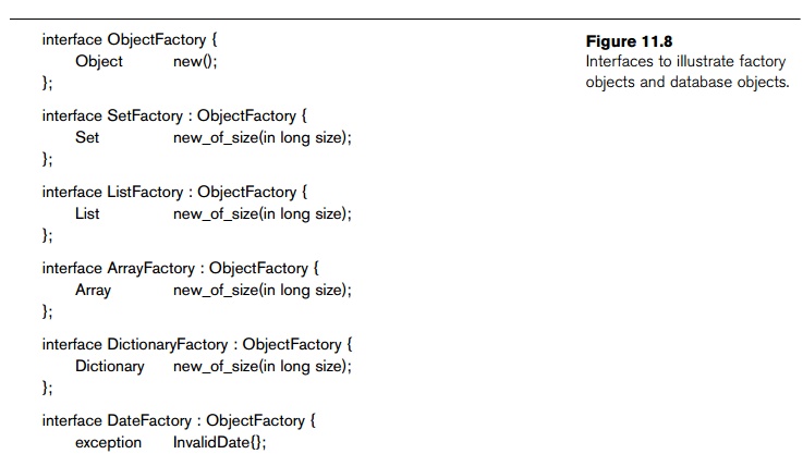
object model are shown in Figure 11.8. The interface ObjectFactory has a single operation, new(), which returns a new object
with an Object_id. By inheriting this interface,
users can create their own factory interfaces for each user-defined (atomic)
object type, and the programmer can implement the operation new differently for each type of object.
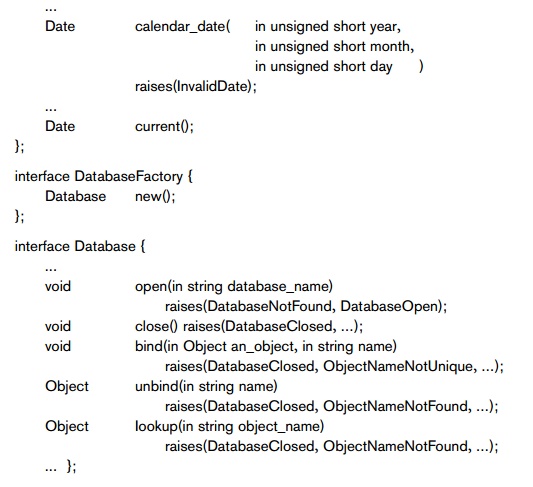
Figure 11.8 also shows a DateFactory
interface, which has additional operations for creating a new calendar_date, and for creating an object
whose value is the current_date, among other operations (not shown in
Figure 11.8). As we can see, a factory object basically provides the constructor operations for new objects.
Finally,
we discuss the concept of a database.
Because an ODBMS can create many different databases, each with its own schema,
the ODMG object model has inter-faces for DatabaseFactory and Database objects, as shown in Figure
11.8. Each data-base has its own database
name, and the bind
operation can be used to assign individual unique names to persistent objects
in a particular database. The lookup
operation returns an object from the database that has the specified object_name, and the unbind operation removes the name of a
persistent named object from the database.
6. The Object
Definition Language ODL
After our
overview of the ODMG object model in the previous section, we now show how
these concepts can be utilized to create an object database schema using the
object definition language ODL.
The ODL
is designed to support the semantic constructs of the ODMG object model and is
independent of any particular programming language. Its main use is to create
object specifications—that is, classes and interfaces. Hence, ODL is not a full
programming language. A user can specify a database schema in ODL
independently of any programming language, and then use the specific language
bindings to specify how ODL constructs can be mapped to constructs in specific
programming languages, such as C++, Smalltalk, and Java. We will give an
overview of the C++ binding in Section 11.6.
Figure
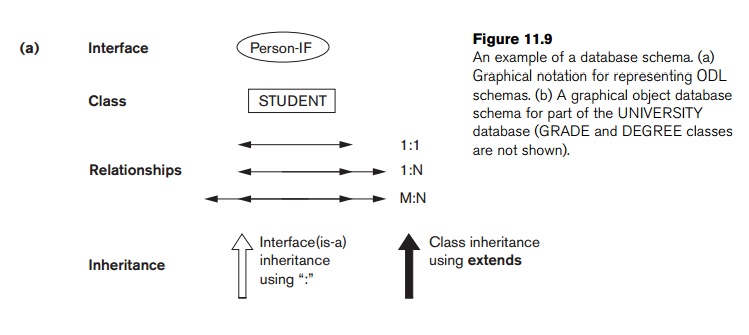
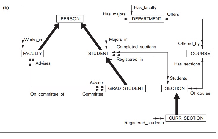
11.9(b) shows a possible object schema for part of the UNIVERSITY database, which was presented in
Chapter 8. We will describe the concepts of ODL using this example, and the one
in Figure 11.11. The graphical notation for Figure 11.9(b) is shown in Figure
11.9(a) and can be considered as a variation of EER diagrams (see Chapter 8)
with the added concept of interface inheritance but without several EER
concepts, such as categories (union types) and attributes of relationships.
Figure
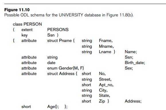
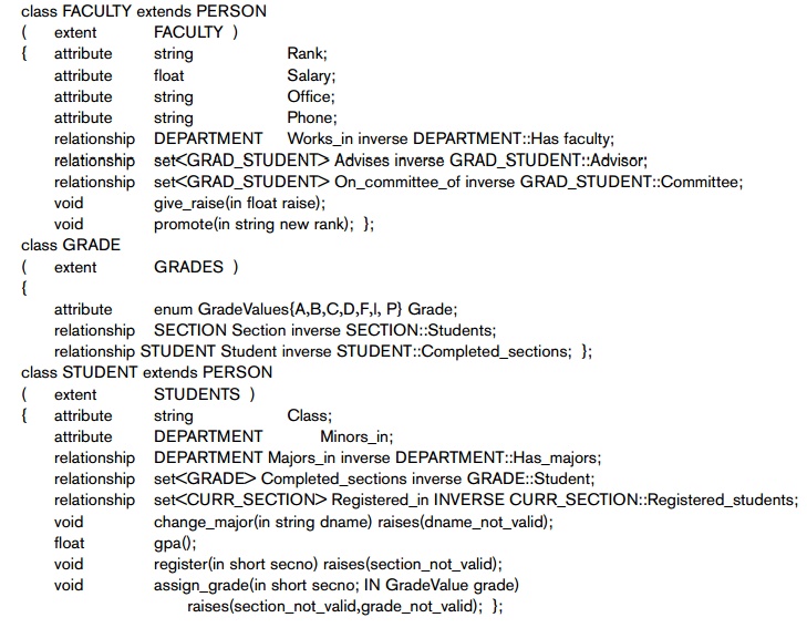
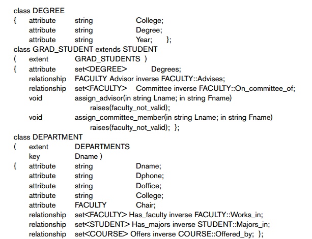
11.10 shows one possible set of ODL class definitions for the UNIVERSITY database. In general, there may
be several possible mappings from an object schema diagram (or EER schema
diagram) into ODL classes. We will discuss these options further in Section
11.4.
Figure
11.10 shows the straightforward way of mapping part of the UNIVERSITY database from Chapter 8. Entity
types are mapped into ODL classes, and inheri-tance is done using extends. However, there is no direct way
to map categories (union types) or to do multiple inheritance. In Figure 11.10
the classes PERSON, FACULTY, STUDENT, and
GRAD_STUDENT have the extents PERSONS, FACULTY, STUDENTS, and
GRAD_STUDENTS, respectively. Both FACULTY and STUDENT extends PERSON and GRAD_STUDENT extends STUDENT. Hence,
the collection of STUDENTS (and the
collection of FACULTY) will be
constrained to be a subset of the
collection
of PERSONs at any time. Similarly, the
collection of GRAD_STUDENTs will be
a subset of STUDENTs. At the
same time, individual STUDENT and FACULTY objects will inherit the
properties (attributes and relationships) and operations of PERSON, and individual GRAD_STUDENT objects will inherit those of STUDENT.
The
classes DEPARTMENT, COURSE, SECTION, and CURR_SECTION in Figure 11.10 are
straightforward mappings of the corresponding entity types in Figure
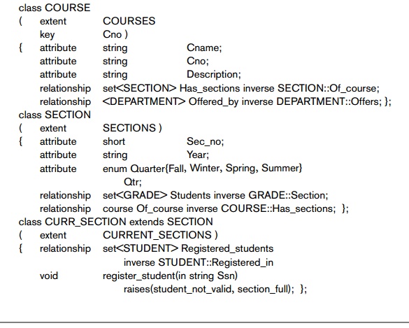
11.9(b).
However, the class GRADE requires
some explanation. The GRADE class
corresponds to the M:N relationship between STUDENT and SECTION in Figure 11.9(b). The reason it
was made into a separate class (rather than as a pair of inverse relationships)
is because it includes the relationship attribute Grade.36
Hence,
the M:N relationship is mapped to the class GRADE, and a
pair of 1:N rela-tionships, one between STUDENT and GRADE and the other between SECTION and GRADE. These relationships are
represented by the following relationship proper-ties: Completed_sections of STUDENT; Section and Student of GRADE; and Students of
SECTION (see Figure 11.10). Finally, the
class DEGREE is used to represent the
com-posite, multivalued attribute degrees of GRAD_STUDENT (see Figure 8.10).
Because
the previous example does not include any interfaces, only classes, we now
utilize a different example to illustrate interfaces and interface (behavior)
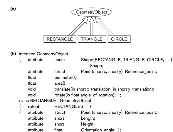
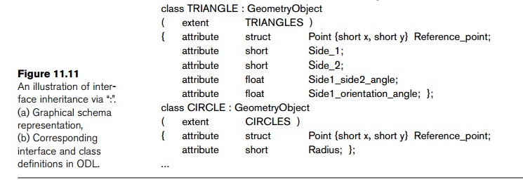
inheri-tance. Figure 11.11(a) is part of a database schema for storing
geometric objects. An interface GeometryObject is
specified, with operations to calculate the perimeter and area of a geometric object, plus
operations to translate (move)
and rotate an object. Several classes (RECTANGLE, TRIANGLE, CIRCLE, ...)
inherit the GeometryObject
interface. Since GeometryObject is an
interface, it is noninstantiable—that
is, no objects can be created based on this interface directly. However,
objects of type RECTANGLE, TRIANGLE, CIRCLE, ... can be created, and these objects inherit all the operations of the GeometryObject interface. Note that with interface
inheritance, only operations are inherited, not properties (attributes,
relationships). Hence, if a property is needed in the inheriting class, it must
be repeated in the class definition, as with the Reference_point attribute in Figure 11.11(b). Notice that the
inherited operations can have different implementations in each class. For
example, the implementations of the area and perimeter operations may be different for
RECTANGLE, TRIANGLE, and
CIRCLE.
Multiple inheritance of
interfaces by a class is allowed, as is multiple inheritance of interfaces by another interface.
However, with the extends (class)
inheritance, mul-tiple inheritance is not
permitted. Hence, a class can inherit via extends from at most one class (in addition to inheriting from zero or more
interfaces).
Related Topics