Chapter: Electronic Devices and Circuits : Feed Back Amplifiers and Oscillators
The Hartley Oscillator
The Hartley Oscillator
The main disadvantages of the basic LC Oscillator circuit we looked at in the previous tutorial is that they have no means of controlling the amplitude of the oscillations and also, it is difficult to tune the oscillator to the required frequency.
If the cumulative electromagnetic coupling between L1 and L2 is too small there would be insufficient feedback and the oscillations would eventually die away to zero Likewise if the feedback was too strong the oscillations would continue to increase in amplitude until they were limited by the circuit conditions producing signal distortion. So it becomes very difficult to "tune" the oscillator.
However, it is possible to feed back exactly the right amount of voltage for constant amplitude oscillations. If we feed back more than is necessary the amplitude of the oscillations can be controlled by biasing the amplifier in such a way that if the oscillations increase in amplitude, the bias is increased and the gain of the amplifier is reduced.
If the amplitude of the oscillations decreases the bias decreases and the gain of the amplifier increases, thus increasing the feedback. In this way the amplitude of the oscillations are kept constant using a process known as Automatic Base Bias.
One big advantage of automatic base bias in a voltage controlled oscillator, is that the oscillator can be made more efficient by providing a Class-B bias or even a Class-C bias condition of the transistor. This has the advantage that the collector current only flows during part of the oscillation cycle so the quiescent collector current is very small.
Then this "self-tuning" base oscillator circuit forms one of the most common types of LC parallel resonant feedback oscillator configurations called the Hartley Oscillator circuit.
Hartley Oscillator Tuned Circuit
In the Hartley Oscillator the tuned LC circuit is connected between the collector and the base of the transistor amplifier. As far as the oscillatory voltage is concerned, the emitter is connected to a tapping point on the tuned circuit coil.
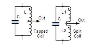
The feedback of the tuned tank circuit is taken from the centre tap of the inductor coil or even two separate coils in series which are in parallel with a variable capacitor, C as shown.
The Hartley circuit is often referred to as a split-inductance oscillator because coil L is centre-tapped. In effect, inductance L acts like two separate coils in very close proximity with the current flowing through coil section XY induces a signal into coil section YZ below.
An Hartley Oscillator circuit can be made from any configuration that uses either a single tapped coil (similar to an autotransformer) or a pair of series connected coils in parallel with a single capacitor as shown below.
Basic Hartley Oscillator Circuit
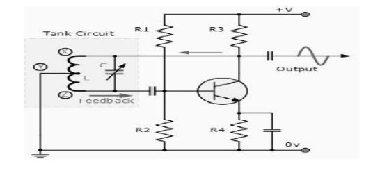
When the circuit is oscillating, the voltage at point X (collector), relative to point Y (emitter), is 180o out-of-phase with the voltage at point Z (base) relative to point Y. At the frequency of oscillation, the impedance of the Collector load is resistive and an increase in Base voltage causes a decrease in the Collector voltage.
Then there is a 180 phase change in the voltage between the Base and Collector and this along with the original 180 phase shift in the feedback loop provides the correct phase relationship of positive feedback for oscillations to be maintained.
The amount of feedback depends upon the position of the "tapping point" of the inductor. If this is moved nearer to the collector the amount of feedback is increased, but the output taken between the Collector and earth is reduced and vice versa.
Resistors, R1 and R2 provide the usual stabilizing DC bias for the transistor in the normal manner while the capacitors act as DC-blocking capacitors.
In this Hartley Oscillator circuit, the DC Collector current flows through part of the coil and for this reason the circuit is said to be "Series-fed" with the frequency of oscillation of the Hartley Oscillator being given as.
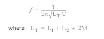
The frequency of oscillations can be adjusted by varying the "tuning" capacitor, C or by varying the position of the iron-dust core inside the coil (inductive tuning) giving an output over a wide range of frequencies making it very easy to tune. Also the Hartley Oscillator produces an output amplitude which is constant over the entire frequency range.
As well as the Series-fed Hartley Oscillator above, it is also possible to connect the tuned tank circuit across the amplifier as a shunt-fed oscillator as shown below.
Shunt-fed Hartley Oscillator Cricuit
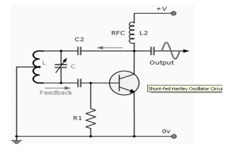
In the Shunt-fed Hartley Oscillator both the AC and DC components of the Collector current have separate paths around the circuit. Since the DC component is blocked by the capacitor, C2 no DC flows through the inductive coil, L and less power is wasted in the tuned circuit.
The Radio Frequency Coil (RFC), L2 is an RF choke which has a high reactance at the frequency of oscillations so that most of the RF current is applied to the LC tuning tank circuit via capacitor, C2 as the DC component passes through L2 to the power supply. A resistor could be used in place of the RFC coil, L2 but the efficiency would be less.
Related Topics