Chapter: Electronic Devices and Circuits : Feed Back Amplifiers and Oscillators
Quartz Crystal Oscillators
Quartz Crystal Oscillators
One of the most important features of any oscillator is its frequency stability, or in other words its ability to provide a constant frequency output under varying load conditions. Some of the factors that affect the frequency stability of an oscillator include: temperature, variations in the load and changes in the DC power supply.
Frequency stability of the output signal can be improved by the proper selection of the components used for the resonant feedback circuit including the amplifier but there is a limit to the stability that can be obtained from normal LC and RC tank circuits.
To obtain a very high level of oscillator stability a Quartz Crystalis generally used as the frequency
When a voltage source is applied to a small thin piece of quartz crystal, it begins to change shape producing a characteristic known as the Piezo-electric effect.
This piezo-electric effect is the property of a crystal by which an electrical charge produces a mechanical force by changing the shape of the crystal and vice versa, a mechanical force applied to the crystal produces an electrical charge.
Then, piezo-electric devices can be classed as Transducersas they convert energy of one kind into energy of another (electrical to mechanical or mechanical to electrical).
This piezo-electric effect produces mechanical vibrations or oscillations which are used to replace the LC tank circuit in the previous oscillators.
There are many different types of crystal substances which can be used as oscillators with the most important of these for electronic circuits being the quartz minerals because of their greater mechanical strength.
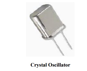
The quartz crystal used in a Quartz Crystal Oscillator is a very small, thin piece or wafer of cut quartz with the two parallel surfaces metallised to make the required electrical connections. The physical size and thickness of a piece of quartz crystal is tightly controlled since it affects the final frequency of oscillations and is called the crystals "characteristic frequency". Then once cut and shaped, the crystal can not be used at any other frequency. In other words, its size and shape determines its frequency.
Quartz Crystal
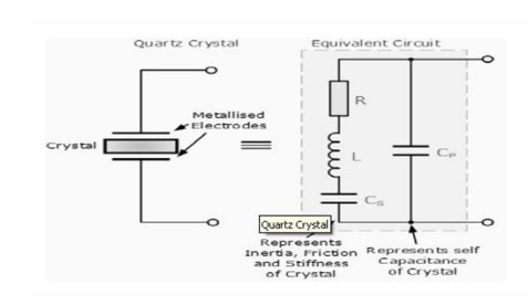
The equivalent circuit for the quartz crystal shows an RLC series circuit, which represents the mechanical vibrations of the crystal, in parallel with a capacitance, Cp which represents the electrical connections to the crystal. Quartz crystal oscillators operate at "parallel resonance", and the equivalent impedance of the crystal has a series resonance where Cs resonates with inductance, L and a parallel resonance where L resonates with the series combination of Cs and Cp as shown.
Crystal Reactance
The slope of the reactance against frequency above, shows that the series reactance at frequency ƒs is inversely proportional to Cs because below ƒs and above ƒp the crystal appears capacitive, i.e. dX/dƒ, where X is the reactance.
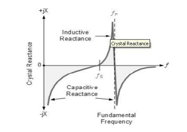
The slope of the reactance against frequency above, shows that the series reactance at frequency fs is inversely proportional to Cs because below fs and above fp the crystal appears capacitive, i.e. dX/d f, where X is the reactance. Between frequencies ƒs and ƒp, the crystal appears inductive as the two parallel capacitances cancel out. The point where the reactance values of the capacitances and inductance cancel each other out Xc = XL is the fundamental frequency of the crystal.
A quartz crystal has a resonant frequency similar to that of a electrically tuned tank circuit butwith a much higher Q factor due to its low resistance, with typical frequencies ranging from 4kHz to
10MHz. The cut of the crystal also determines how it will behave as some crystals will vibrate at more than one frequency. Also, if the crystal is not of a parallel or uniform thickness it has two or more resonant frequencies having both a fundamental frequency and harmonics such as second or third harmonics. However, usually the fundamental frequency is more stronger or pronounced than the others and this is the one used. The equivalent circuit above has three reactive components and there are two resonant frequencies, the lowest is a series type frequency and the highest a parallel type resonant frequency.
We have seen in the previous tutorials, that an amplifier circuit will oscillate if it has a loop gain greater or equal to one and the feedback is positive. In a Quartz Crystal Oscillator circuit the oscillator will oscillate at the crystals fundamental parallel resonant frequency as the crystal always wants to oscillate when a voltage source is applied to it.
Colpitts Crystal Oscillator:
The design of a Crystal Oscillator is very similar to the design of the Colpitts Oscillator we looked at in the previous tutorial, except that the LC tank circuit has been replaced by a quartz crystal as shown below.
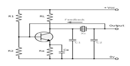
These types of Crystal Oscillators are designed around the common emitter amplifier stage of a Colpitts Oscillator. The input signal to the base of the transistor is inverted at the transistors output.
The output signal at the collector is then taken through a 180o phase shifting network which includes the crystal operating in a series resonant mode. The output is also fed back to the input which is "in-phase"
with the input providing the necessary positive feedback. Resistors, R1 and R2 bias the resistor in aClass
A type operation while resistor
Re is chosen so that the loop gain is slightly greater than unity.
Capacitors, C1 and C2 are made as large as possible in order that the frequency of oscillations can approximate to the series resonant mode of the crystal and is not dependant upon the values of these capacitors.
The circuit diagram above of the Colpitts Crystal Oscillator circuit shows that capacitors, C1 and C2 shunt the output of the transistor which reduces the feedback signal.
Therefore, the gain of the transistor limits the maximum values of C1 and C2.
The output amplitude should be kept low in order to avoid excessive power dissipation in the crystal otherwise could destroy itself by excessive vibration.
Pierce Oscillator
The Pierce oscillator is a crystal oscillator that uses the crystal as part of its feedback path and therefore has no resonant tank circuit. The Pierce Oscillator uses a JFET as its amplifying device as it provides a very high input impedance with the crystal connected between the output Drain terminal and the input Gate terminal as shown below.
Pierce Crystal Oscillator
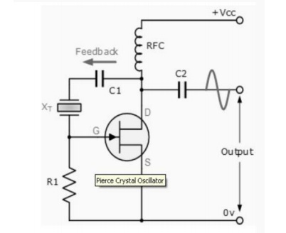
In this simple circuit, the crystal determines the frequency of oscillations and operates on its series resonant frequency giving a low impedance path between output and input.
There is a 180° phase shift at resonance, making the feedback positive. The amplitude of the output sine wave is limited to the maximum voltage range at the Drain terminal.
Resistor, R1 controls the amount of feedback and crystal drive while the voltage across the radio frequency choke, RFC reverses during each cycle. Most digital clocks, watches and timers use a Pierce Oscillator in some form or other as it can be implemented using the minimum of components.
Related Topics