Chapter: Electronic Devices and Circuits : Feed Back Amplifiers and Oscillators
Oscillators
Oscillators:
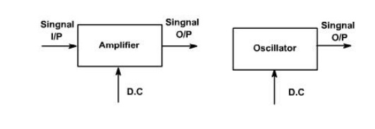
An oscillator may be described as a source of alternating voltage. It is different than amplifier.
An amplifier delivers an output signal whose waveform corresponds to the input signal but whose power level is higher. The additional power content in the output signal is supplied by the DC power source used to bias the active device.
The amplifier can therefore be described as an energy converter, it accepts energy from the DC power supply and converts it to energy at the signal frequency. The process of energy conversion is controlled by the input signal, Thus if there is no input signal, no energy conversion takes place and there is no output signal.
The oscillator, on the other hand, requires no external signal to initiate or maintain the energy conversion process. Instead an output signals is produced as long as source of DC power is connected. Fig. 1, shows the block diagram of an amplifier and an oscillator.
Oscillators may be classified in terms of their output waveform, frequency range components, or circuit configuration.
If the output waveform is sinusoidal, it is called harmonic oscillator otherwise it is called relaxation oscillator, which include square, triangular and saw tooth waveforms.
Oscillators employ both active and passive components. The active components provide energy conversion mechanism. Typical active devices are transistor, FET etc.
Passive components normally determine the frequency of oscillation. They also influence stability, which is a measure of the change in output frequency (drift) with time, temperature or other factors. Passive devices may include resistors, inductors, capacitors, transformers, and resonant crystals.
Capacitors used in oscillators circuits should be of high quality. Because of low losses.
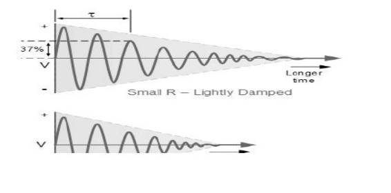
Damped Oscillations
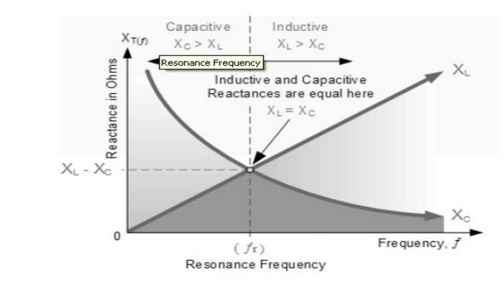
The frequency of the oscillatory voltage depends upon the value of the inductance and capacitance in the LC tank circuit. We now know that for resonance to occur in the tank circuit, there must be a frequency point were the value of XC, the capacitive reactance is the same as the value of XL, the inductive reactance (XL = XC) and which will therefore cancel out each other out leaving only the DC resistance in the circuit to oppose the flow of current.
If we now place the curve for inductive reactance on top of the curve for capacitive reactance so that both curves are on the same axes, the point of intersection will give us the resonance frequency point, ( ƒr or ωr ) as shown below.
Resonance Frequency
where: ƒr is in Hertz, L is in Henries and C is in Farads. Then the frequency at which this will happen is given as:
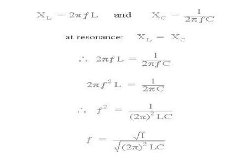
Then by simplifying the above equation we get the final equation for Resonant Frequency, ƒr in a tuned LC circuit as:
Resonant Frequency of a LC Oscillator
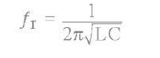
Where:
L is the Inductance in Henries C is the Capacitance in Farads ƒr is the Output Frequency in Hertz
This equation shows that if either L or C are decreased, the frequency increases. This output frequency is commonly given the abbreviation of ( ƒr ) to identify it as the "resonant frequency". To keep the oscillations going in an LC tank circuit, we have to replace all the energy lost in each oscillation and also maintain the amplitude of these oscillations at a constant level.
The amount of energy replaced must therefore be equal to the energy lost during each cycle. If the energy replaced is too large the amplitude would increase until clipping of the supply rails occurs. Alternatively, if the amount of energy replaced is too small the amplitude would eventually decrease to zero over time and the oscillations would stop.
The simplest way of replacing this lost energy is to take part of the output from the LC tank circuit, amplify it and then feed it back into the LC circuit again. This process can be achieved using a voltage amplifier using an op-amp, FET or bipolar transistor as its active device.
However, if the loop gain of the feedback amplifier is too small, the desired oscillation decays to zero and if it is too large, the waveform becomes distorted. To produce a constant oscillation, the level of the energy fed back to the LC network must be accurately controlled.
Then there must be some form of automatic amplitude or gain control when the amplitude tries to vary from a reference voltage either up or down. To maintain a stable oscillation the overall gain of the circuit must be equal to one or unity. Any less and the oscillations will not start or die away to zero, any more the oscillations will occur but the amplitude will become clipped by the supply rails causing distortion. Consider the circuit below.
Basic Transistor LC Oscillator Circuit
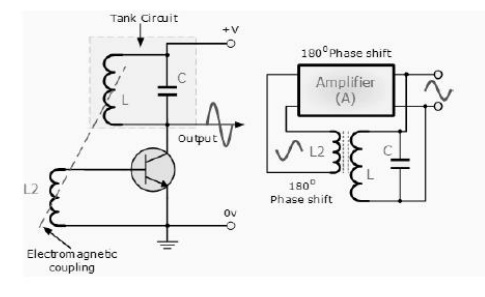
A Bipolar Transistor is used as the LC oscillators amplifier with the tuned LC tank circuit acts as the collector load. Another coil L2 is connected between the base and the emitter of the transistor whose electromagnetic field is "mutually" coupled with that of coil L. Mutual inductance exists between the two circuits.
The changing current flowing in one coil circuit induces, by electromagnetic induction, a potential voltage in the other (transformer effect) so as the oscillations occur in the tuned circuit, electromagnetic energy is transferred from coil L to coil L2 and a voltage of the same frequency as that in the tuned circuit is applied between the base and emitter of the transistor.
In this way the necessary automatic feedback voltage is applied to the amplifying transistor. The amount of feedback can be increased or decreased by altering the coupling between the two coils L and L2. When the circuit is oscillating its impedance is resistive and the collector and base voltages are 180 out of phase. In order to maintain oscillations (called frequency stability) the voltage applied to the tuned circuit must be "in-phase" with the oscillations occurring in the tuned circuit.
Therefore, we must introduce an additional 180o phase shift into the feedback path between the collector and the base. This is achieved by winding the coil of L2 in the correct direction relative to coil L giving us the correct amplitude and phase relationships for the Oscillatorscircuit or by connecting a phase shift network between the output and input of the amplifier.
TheLC Oscillator is therefore a "Sinusoidal Oscillator" or a "Harmonic Oscillator" as it is more commonly called. LC oscillators can generate high frequency sine waves for use in radio frequency (RF) type applications with the transistor amplifier being of a Bipolar Transistor or FET.
Harmonic Oscillators come in many different forms because there are many different ways to construct an LC filter network and amplifier with the most common being the Hartley LC Oscillator, Colpitts LC Oscillator, Armstrong OscillatorandClapp Oscillator to name a few.
Related Topics