Chapter: Mechanical : Mechatronics : Actuation System
System Models and Controllers Building
SYSTEM MODELS
AND CONTROLLERS BUILDING
BLOCKS OF
MECHANICAL SYSTEM:
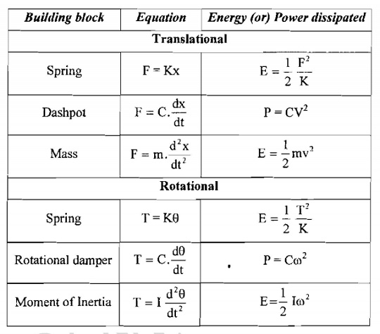
BLOCKS OF MECHANICAL SYSTEM:BUILDING
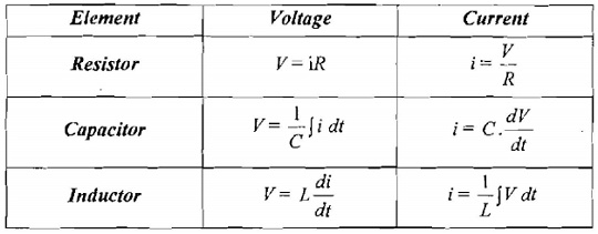
BLOCKS OF ELECTRICAL SYSTEM:
TYPES OF CONTROL MODES:
The Two – Step Mode:
The two-step mode in which the controller is essentially just
a switch which is activated by the error signal and supplied just an on-off
correcting signal.
An example of the two-step mode of control is the
bimetallic thermoset at that might be used with a simple temperature control
system.
This is just a switch which is switched on or off
according to the temperature then the bimetallic ship is in an off position and
the heater is off.
If the room temperature falls below the required
temperature then the bimetallic strip moves into an on position and the heater
is switched fully on. The controller in this case
can be in
only two positions, on or off.
The
Proportional Mode (P):
The proportional mode (P) which products a control
action that is proportional to the error. The correcting signal thus becomes
bigger the bigger the error.
Thus as
the error is reduced the amount of correction is reduced and the correcting
process slows down.
The
proportional mode, the size of the controller output is proportional to the
size of the error.
K = 100 / Proportional
Band
Change
in Output (s) = Kp
* E(s)
Transformer
function = Change
in Output (s) / E(s)
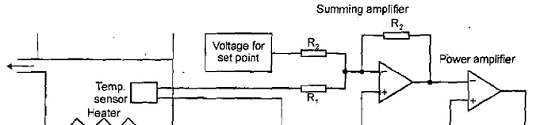
Electronic Proportional Controller:
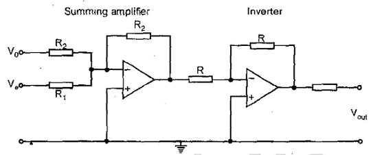
Example for Proportional Controller:
The Derivative Mode (D):
The derivative mode (D) which products a control action that
is proportional to the rate at which are errors is changing.
When
there is a sudden change in the error signal the controller gives a large
correcting signal
When there is a gradual change only a small corrections signal
is produced. Derivative control can be considered to be a form of anticipatory
control in that the existing rate of
change of
error is measured, a coming larger error is anticipated and correction applied
before
the larger error has arrived.
Derivative mode of control the change in controller output
from the set point value is proportional to the rate of change with time of the
error signal
t – IO =
KD
Proportional Plus Derivative Mode:
Change in
output from the set point = KP e + KD
Iout
= KP e + KD + I0
The Integral Mode (I):
The integral mode (I) which produces a control action that is
proportional to the integral of the error with time.
Thus a constant error signal will produce an increasing
correcting signal. The correction continues to increase as long the error
persists.
The integral mode of control is one where the rate of change
of the control output I is proportional to the input error signal.
Proportional
Plus Integral Control:
Iout = KP e + KI ∫ +
IO
Transfer Function
= Kp + = (S + )
Combinations of Modes:
Proportional plus derivative modes (PD), proportional plus
integral modes (PI), proportional plus integral plus derivative modes (PID).
The term
three – term controller is used for PID control.
DIGITAL CONTROLLERS:
The tern digital control is used when the digital controller,
basically a microprocessor is in control of the closed-loop control system.
The
controller receives inputs from sensors, executes control programs and provides
the output to the correction elements.
The controllers require inputs which are digital, process the
information in digital form and give an output in digital form.
Since many control systems have analogue measurements an
analogue-to-digital converter (ADC) is used forth inputs.
A clock supplies a pulse at regular time intervals and
dictates when samples of the controlled variable are taken by the ADC.
The samples
are then converted
to digital signals
which are compared
by the
microprocessor
with the set point value to give the error signal.
The
microprocessor can then initiate a control mode to process the error signal and
give a digital output.
The control mode used by the microprocessor is determined by
the program of instruction used by the microprocessor for processing the
digital signals, i.e., the
software.
The digital output, generally after processing by a
digital-to-analogue converter since correcting elements generally require
analogue signals can be used to initiate the
correcting
action
A digital
controller basically operates the following cycle of events:
Samples
the measured value.
Compares
it with the set value and establishes the error.
Carries out calculations based on the error value and stored
values of previous inputs and outputs to obtain the output signal
Sends the
output signal to the DAC.
Waits
until the next sample time before repeating the cycle.
VELOCITY CONTROL:
Consider
the problem of controlling the movement of a load by means of a motor.
Time will
thus be taken for the system to respond to an input signal.
A higher speed of respond, with fewer oscillations, can be
obtained by using PD rather than just P control.
There is, however, alternative of achieving the same effect
and this is by the use of a second feedback loop which gives a measurement
related to the rate at which the
displacement
is changing.
This is
termed velocity feedback.
The velocity feedback might involve the use of a
Tachogenerator giving a signal proportional to the rotational speed of the
motor shaft and hence the rate at which the
displacement
is changing and the displacement might be monitored using a rotary
potentiometer
ADAPTIVE CONTROL:
An adaptive control system which 'adapts' to changes and
changes its parameters to fit the circumstances prevailing.
The
adaptive control system is based on the use of a microprocessor as the
controller.
Such a
device enables the control mode and the control parameters used to be adapted
to fit the circumstances, modifying them as the circumstances change.
Stages of Adaptive Control System:
An
adaptive control system can be considered to have three stages of operation.
Starts to
operate with controller conditions set on the basis of an assumed condition.
The
desired performance is continuously compared with the actual system
performance.
The control system mode and parameters are automatically and
continuously adjusted in order to minimise the difference between the desired
and actual system performance.
Forms of Adaptive Control System:
Adaptive control systems can take a number of forms. Three
commonly used forms are: Gain-scheduled control
Self –
tuning
Model-reference
adaptive systems
Gain – Scheduled Control:
With gain-scheduled control or, as it is sometimes referred
to, pre-programmed adaptive control, pre-set changes in the parameters of the
controller are made on the basis of some
auxiliary
measurement of some process variable.
The term
gain-scheduled control was used because the only parameter originally adjusted
was gain
Self – Tuning:
With self-tuning control the system continuously tunes its own
parameters based on monitoring the variable that the system is controlling and
the output from the controller.
Self-tuning is often found in commercial PID controller, it
generally then being referred to as auto-tuning.
When the operator presses a button, the controller injects a
small disturbance into the system and measures the response.
Response is compared to the desired response and the control
parameters adjusted, by modified Ziegler-Nichol rule, to bring the actual
response closer to the desired response.
Model-Reference Adaptive Systems:
The
model-reference system an accurate model of the system is developed.
The set value is then used as an input to both the actual and
the model systems and the difference between the actual output and the output
from the model compared. The difference in these signals is then used m adjusts
the parameter of the controller to minimise the difference.
Related Topics