Chapter: Civil : Structural Analysis : Flexibility Method
Structural Analysis: Flexibility Method
FLEXIBILITY METHOD
INTRODUCTION
These are the two basic methods
by which an indeterminate skeletal structure is analyzed. In these methods
flexibility and stiffness properties of members are employed. These methods
have been developed in conventional and matrix forms. Here conventional methods
are discussed.
suitable number of releases. The
number of releases required is equal to staticalindeterminacy s. Introduction of
releases results in displacement discontinuities at these releases under the
externally applied loads. Pairs of unknown biactions (forces and moments) are applied
at these releases in order to restore the continuity or compatibility of
structure.
The computation of these unknown
biactions involves solution of? linear
simultaneous equations. The number of these equations is equal to staticalindeterminacy
s. After the unknown biactions are computed all the internal forces can be computed
in the entires tructure using equations of equilibrium and free bodies of members.
The required displacements can also be computed using methods of displacement
computation.
Inflexibility methods inceunknowns
are forces at the releases the method is also called force method. Since
computation of displacement is also required at releases for imposing
conditions of compatibility the method is also called compatibility method. In
computation of displacements use is made of flexibility properties, hence, the method
is also called flexibility method.
EQUILIBRIUM and COMPATABILITY CONDITIONS
Thethreeconditionsofequilibriumarethesumofhorizontalforces,verticalforcesandmom
ents at anyjoint should beequal to zero.
i.e.?H=0;?V=0;?M=0
Forces should be in equilibrium
i.e.?FX=0;?FY=0;?FZ=0
i.e.?MX=0;?MY=0;?MZ=0
Displacement of a structure should be compatable
The compatibility conditions for the supports can be given as
1.Roller Support ?V=0 2.Hinged
Support ?V=0, ?H=0
3.Fixed Support ?V=0, ?H=0, ??=0
DETERMINATE AND INDETERMINATE STRUCTURAL SYSTEMS
If skeletal structure is subjected
to gradually increasing loads, without distorting the initial geometry of structure,
that is, causing small displacements, the structure is said to be stable.
Dynamic loads and buckling or instability of structural system are not
considered here. Ifforthestable structure it is possible to find the internal forces
in all the members constituting the structure and supporting reactions at all
the supports provided from statically equations of equilibrium only, the structure
is said to be determinate.
If it is possible to determine all
the support reactions from equations of equilibrium alone the structure is said
to be externally determinateelse externally indeterminate. If structure is
externally determinatebutitis not possible to determine all internal forces then
structure is said to be internally indeterminate. There foreastructural system may
be:
(1)Externally indeterminate but internally determinate
(2)Externally determinate but internally indeterminate
(3)Externally and internally indeterminate
(4)Externally
and internally determinate
DETERMINATEVs
INDETERMINATESTRUCTURES.
Determinate structures can be solving
using conditions of equilibrium alone (?H=0;?V=0 ;?M=0). No
other conditions are required.
Indeterminate structures cannot be
solved using conditions of equilibrium because (?H?0; ?V?0;?M?0). Additional
conditions are required for solving such structures.
Usually
matrix methods are adopted.
INDETERMINACYOF STRUCTURAL SYSTEM
The indeterminacy of a structure
is measured as statically (?s) or
kinematical (?k) Indeterminacy.
?s= P (M - N + 1) - r = PR- r ?k= P (N - 1) + r - s+?k= PM -c P = 6
for space frames subjected to general loading
P = 3 for plane frames subjected
to inplane or normal to plane loading. N = Numberof nodes in structural system.
M=Numberofmembersofcompletelystiffstructurewhichincludesfoundationas
singly connected system of members.
Incompletely stiff structure thereisnorelease
present. In singly connected system of rigid foundation members there is only one
route between any two points in which tracks
are not retraced. The system is considered comprising of closed rings or loops.
R = Number of loops or rings in
completely stiff structure. r = Number of releases in the system.
c = Number of constraints in the
system. R = (M - N + 1)
For plane and space
trusses ?sr educes to:?s=M-
(NDOF)N+ P
![]() M= Number of members in
completely stifftruss.
M= Number of members in
completely stifftruss.
P = 6 and 3 for space and plane truss respectively
![]()
N= Number of nodes in truss.
NDOF = Degrees of freedomat node
which is 2 for plane truss and 3 for space truss. For space truss?s=M- 3N+ 6
For plane truss?s= M- 2 N+
3
![]()
![]()
![]()
![]()
Test for static indeterminacy of structural system
If ?s> 0 Structure is statically indeterminate
If ?s= 0
Structure is statically determinate
and if?s<0
Structure is a mechanism.
It may be noted that structure may
be mechanism even if ?s >0 if thereleases are present
in such away so as to cause collapse as mechanism. The situation of mechanism
is unacceptable.
Statically Indeterminacy
It is difference of the unknown forces
(internal forces plusexternal reactions) and the equations of equilibrium.
Kinematic Indeterminacy
It is the number of possible relative
displacement softhenodes in the directions of stress resultants.
PRIMARY STRUCTURE
A structure formed by the removing the excess or redundant
restraints from an indeterminate structure making it statically determinate is
called primary structure. This is required for solving indeterminate structures
by flexibility matrix method.
Indeterminate structure Primary Structure

ANALYSIS OF INDETERMINATE STRUCTURES :BEAMS
1Introduction
·
Solve statically
indeterminate beams of degree more than one.
·
To solve the problem in matrix notation.
·
To compute reactions at all the supports.
·
To compute internal resisting bending moment at
any section of the continuous beam.
Beams which are statically indeterminate to first degree, were
considered. If the structure is statically indeterminate to a degree more than
one, then the approach presented in the force method is suitable.
Problem 1.1
Calculate the support reactions in the continuous
beam ABC due to loading as shown in Fig.1.1 Assume EI to be constant throughout.
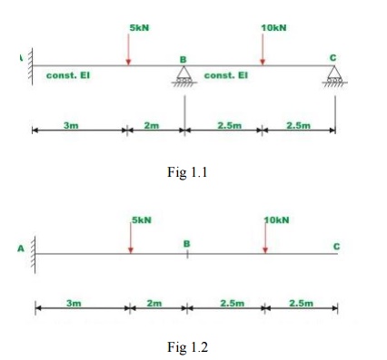
Select two reactions vise, at
B(R1 ) and C(R2 ) as redundant, since the given beam is statically
indeterminate to second degree. In this case the primary structure is a
cantilever beam AC. The primary structure with a given loading is shown in Fig.
1.2
In the present case, the
deflections (? L)1 and (? L) 2 of the released structure at B and C
can be readily calculated by moment-area method. Thus
(? L) 1 =
? 819.16 / EI
(? L) 2 =
? 2311.875/ EI (1)
For the present problem the flexibility matrix is,
a11= 125/3EI ,a21= 625/6EI
a12= 625/6EI , a22 = 1000/3EI (2)
In
the actual problem
the displacements at B and Care
zero. Thus the
compatibility conditions for the
problem may be written as, a11 R1+ a12 R2 + (? L) 1 = 0
a21 R1+ a22 R2+ (? L) 2 = 0(3)
Substituting the value of E and I in the above equation,
R1 = 10.609 KN and R2 = 3.620 KN
Using equations of static equilibrium, R3 = 0.771 KN m and R4
= ?0.755KN m
Problem 1.2
A Fixed beam AB
of
constant flexural rigidity is shown in Fig.1.3 The beam is subjected to auniform
distributed load of w moment M=wL2 kN.m. Draw Shear
force and bending moment diagrams by force method.
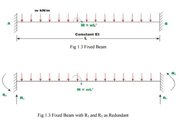
Fig 1.3 Fixed Beam with R1 and R2 as Redundant
Select vertical reaction (R1)and the support
moment(R2) at B as the redundant. The primary
structure in this case is acantilever beam which could be obtained by releasing the redundant R1
andR2.
The R1 is assumed to positive in the upward direction and R2 is assumed to be positive in the
counterclockwise direction. Now, calculate deflection at B duetoonly applied
loading. Let ( L ) be the transverse deflection
at1 B and( L 2 bethe
slope at B due to external loading.
The positive directions of the selected redundant are shown in Fig.8.3b.
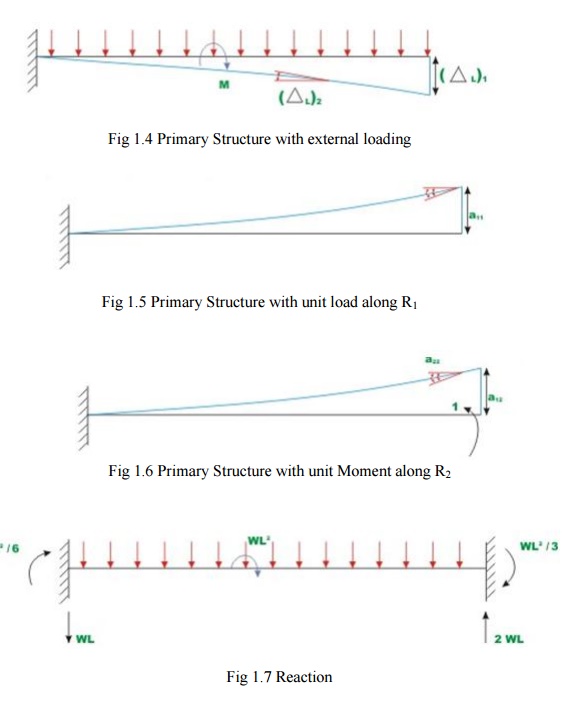
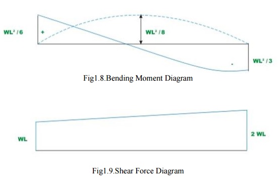
The deflection(? L1)and(?
L2)of the
released structure can be evaluated from unit load
method.
Thus,
(? L1) =wL4/8EI
- 3wL4/8EI
=
?wL4/2EI
- (1)
(? L2) = wL3/6EI
- wL3 /2EI =
? 2wL3/3EI --- -(2)
The negative sign indicates that ( L )is downwards
and rotation( is 1 L2) clockwise.
Problem 1.3.
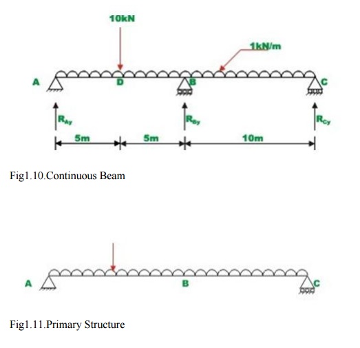
A continuous beam ABC is carrying a uniformly
distributed load of 1 kN/m in addition to a concentrated load of 10kN as shown in
Fig.7.5a, Draw bending moment and shear force diagram. Assume EI to be constant
for all members.
It is observed that the continuous beam is statically
indeterminate to first degree. Choose the reaction at B, RBy
as the redundant. The primary structure is a simply supported beam as shown in Fig.1.11.
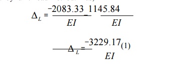
Now, compute the deflection at B, in the released structure due to uniformly
distributed load and concentrated load. This is accomplished by unit load
method. Thus,
In thenextstep,
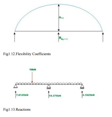
apply a unit load at B in the direction of
RBy(upwards)and
Calculate the deflection at B of the following
structure. Thus(seeFig.7.5c),

Now, deflection at B in the primary structure due
to redundant RB is,

In the actual structure, the deflection at B is
zero. Hence, the compatibility equation may be written as

L+ B=0(4)
The other
two reactions are calculated by static equilibrium equations (videFig.
1.13)
RA
=7.8125kN
RB
=2.8125kN
Related Topics