Chapter: Mechanical : Strength of Materials : Thin Cylinders, Spheres and Thick Cylinders
Stresses on inclined plane
Stresses on inclined plane
Stresses on inclined plane
procedure to tackle stresses on inclined planes
STEPS:
In order to do achieve the desired objective we proceed in the following manner
(i) Label the Block ABCD.
(ii) Set up axes for the direct stress (as abscissa) and shear stress (as ordinate)
(iii) Plot the stresses on two adjacent faces e.g. AB and BC, using the following sign convention.
tensile positive; compressive, negative Shear stresses –tending to turn block clockwise, positive
–tending to turn block counter clockwise, negative
[ i.e shearing stresses are +ve when its movement about the centre of the element is clockwise ]
This gives two points on the graph which may than be labeled as respectively to denote stres these planes.
(iv) Join AB bar and BC bar.
(v) The point P where this line cuts the s axis is than the centre of Mohr's stress circle and th joining AB bar and BC bar is diameter. Therefore the circle can now be drawn.
Now every point on the circle then represents a state of stress on some plane through C.
Principal planes and stresses
Principal stresses and planes
Principal Directions, Principal Stress
x' andy' (x'y') vary smoothly with respect to the rotation accordance with the coordinate transformation equations. There exist a couple of particular angles wher take on special values.
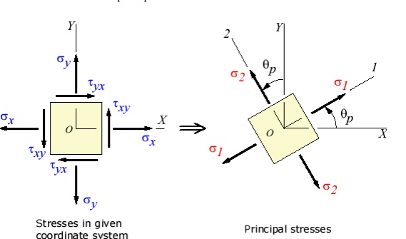
First, there exists an angle p where the shear stress x'y' becomes zero. That angle is found by setting the above shear transformation equation and solving for (set equal to p). The result is,

The angle p defines the principal directions where the only stresses are normal stresses. These called principal stresses and are found from the original stresses (expressed in the x,y,z directions) via,

The transformation to the principal directions can be illustrated as:

Maximum Shear Stress Direction
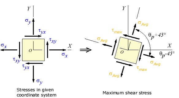
s, is where the maximum shear stress occurs. This is found by finding the ma. Another important angle, shear stress transformation equation, and solving for

The maximum shear stress is equal to one-half the difference between the two principal stresses,

The transformation to the maximum shear stress direction can be illustrated as:

Related Topics