Chapter: Power System Operation and Control : Real Power Frequency Control
Speed Governing Mechanism and Modelling
SPEED GOVERNING MECHANISM AND MODELLING
Governor:
The power system is basically dependent upon the synchronous generator and its satisfactory performance. The important control loops in the system are:
(i) Frequency control, and
(ii) Automatic voltage control.
Frequency control is achieved through generator control mechanism. The governing systems for thermal and hydro generating plants are different in nature since, the inertia of water that flows into the turbine presents additional constrains which are not present with steam flow in a thermal plant. However, the basic principle is still the same; i.e. the speed of the shaft is sensed and compared with a reference, and the feedback signal is utilized to
increase or decrease the power generated by controlling the inlet valve to turbine of steam or water
Speed Governing Mechanism
The speed governing mechanism includes the following parts.
Speed Governor:
It is an error sensing device in load frequency control. It includes all the elements that are directly responsive to speed and influence other elements of the system to initiate action.
Governor Controlled Valves:
They control the input to the turbine and are actuated by the speed control mechanism.
Speed Control Mechanism:
It includes all equipment such as levers and linkages,servomotors, amplifying devices and relays that are placed between the speed governor and the governor controlled valves.
Speed Changer:
It enables the speed governor system to adjust the speed of the generator unit while in operation.
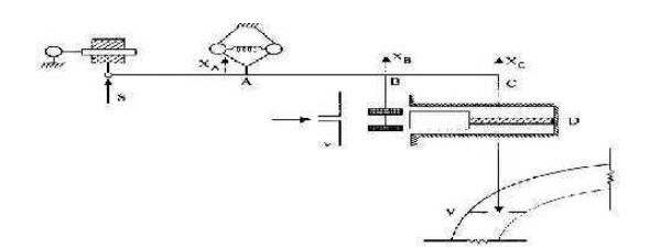
The pilot valve v operates to increase or decrease the opening of the steam inlet valve V. Let XB and Xc be the changes in the position of the pilot valve v and control valve V responding to a change in governor position. XA due to load. When the pilot valve is closed XB= 0 and Xc == 0, (Le.,) the control valve is not completely closed, as the unit has to supply its no-load losses. Let be the no-load angular speed of the turbine. As load is applied, the speed falls and through the linkages the governor operates to move the piston P downwards along with points A and B. The pilot valve v admits soil under n and lifts it up so that the input is increased and speed rise. If the link Be is removed then the pilot valve comes to rest only when the speed returns to its original value. An "isochronous" characteristic will be obtained with such an arrangement where speed is restored to its preload.
With the link Be, the steady state is reached at a speed slightly lower than the no load speed giving a drooping characteristic for the governor system. A finite value of the steady state speed regulation is obtained with this arrangement. For a given speed changer position, the per unit steady state speed regulation is defined by
Steady state speed regulation = No-Nr/N Where No = Speed at no - load
Nr = Rated speed
N = Speed at rated load
Related Topics