Chapter: Civil : Structural Analysis : Space And Cable Structures
Space and Cable Structures
SPACE AND CABLE STRUCTURES
1 ANALYSIS OF SPACE TRUSSES USING METHOD OF TENSION
COEFFICIENTS
1.1. Tension Co-efficient Method
The tension co efficient for a
member of a frame is defined as the pull or tension in that member is divided
by its length.
t = T/l Where t = tension co
efficient for the member
T= Pull in the member
l = Length
1.2. Analysis Procedure Using Tension Co-efficient
- 2D
Frames
1. List the coordinates of each joint (node)of the truss.
2. Determine the projected
lengths Xij and Yij of each member of the truss.
Determine the support lengths lij of each member using the equation
lij =?Xij2+Yij2
3. Resolve the the applied the
forces at the joint in the X and Y directions. Determine the support reactions
and their X and Y components.
4. Identify a node with only two
unknown member forces and apply the equations of equilibrium. The solution
yields the tension co efficient for the members at the node.
5. Select the next joint with
only two unknown member forces and apply the equations of equilibrium and apply
the tension co efficient.
6. Repeat step 5 till the tension
co efficient of all the members are obtained. 7. Compute the member forces from
the tension co efficient obtained as above using
Tij= tijx lij
1.3. Analysis Procedure Using Tension Co-efficient
- Space
Frames
1. In step 2 above the projected
lengths Zij in the directions are also computed. Determine the support lengths
lij of each member using the equation lij =?Xij2+Yij2
+Zij2
2. In step 3 above the components
of forces and reactions in the Z directions are also to be determined.
3. In step 4 and 5,each time,
nodes with not more than three unknown member forces are to be considered.
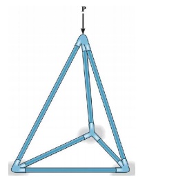
Tetrahedron: simplest element
of stablespacetruss ( six members, four joints)
expand by adding 3members and1jointeachtime
Determinacy and Stability b+r <3j
unstable
b+r=3j statically determinate (check stability)
b+r>3j
statically indeterminate (check stability)
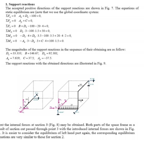
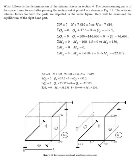
Internal Forces
In order to obtain the internal forces
at a specified point, we should make section cut perpendicular to the axis of the
member at this point. This section cut divides the structure in two parts. The portion
of the structure removed from the part in to consideration should be replaced by the internal forces. The internal forces ensure
the equilibrium of the isolated part subjected to the action of external loads and
support reactions. A free body diagram of either segment of the cut member is isolated and the internal loads
could be derived by the six equations of equilibrium applied to the segment in to
consideration.
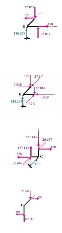
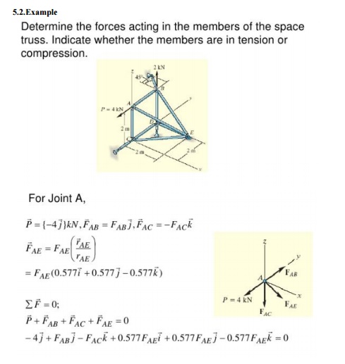
5.1. Example
In the following
example we shall construct the internal forces diagrams for the given in Fig. space
frame structure. The introduced global coordinate system is shown in the same figure.
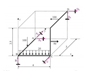
The
introduced local coordinate systems of the different elements of the space
frame are presented in Fig. The typical sections where the internal forces must be calculated,
in order to construct the relevant diagrams, are numbered from 1 to 8 in the same
figure. The typical sections are placed atleast
at the beginning and at the end of each element (segment) of the frame. The internal
forces diagrams, in the limits of each element, could be derived by using the
corresponding reference and base diagrams.
2 BEAMS CURVED IN PLAN
2.1Introduction
Arches are in fact beams with an
initial curvature. The curvature is visible only in elevation. In plan they
they would appear in straight. the other cases of curved beams are ring beams
supporting water tanks, Silos etc., beams supporting corner lintels and curved
balconies etc., Ramps in traffic interchanges invariably have curved in plan
beams.
Curved beams in addition to the
bending moments and shears would also develop torsional moments.
2.2. Moment, Shear and Torsion
The three diverse force
components have one thing in common - the
strain energy stored in a beam due to each type of force. Among the 3 we
normally ignore the strain energy due to shear forces as negligible.
U = ?M2ds/2EI+?T2ds/2GJ
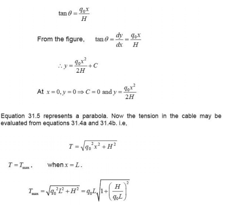
3. SUSPENSION CABLE
3.1. Indroduction
Cables and archesareclosely
related to each other and hence they are grouped in this course in the same module.
For long span structures (fore.g.in case bridges) engineers commonly use cable or
arch construction due to their efficiency. In the few previous pages, cables
subjected to uniform and concentrated loads
are discussed. In the few previous pages, arches in general and threehingedarchesin
particular along with illustrative examples are explained.
In the last few pages, two hinged
arch and hinge less arches are considered. Structure may be classified into
rigid and deformable structures depending on change in geometry of the structure
while supporting the load. Rigid structures support externally applied loads without
appreciable change in their shape (geometry). Beams trusses and frames are
examples of rigid structures.
Unlike rigid structures, deformable structures undergo changes
in their shape according to externally applied loads. However, it should be noted
that deformations are stillsma ll. Cables and fabric structures are deformable structures.
Cables are mainly used to support suspension roofs, bridges and cable car system.
They are also used in electrical transmission lines and for structure
supporting radio antennas. In the following sections, cables subjected to concentrated
load and cables subjected to uniform loads are considered.
The shape assumed by
aropeorachain (with no stiffness) under the action of external loads when hung from
two supports is known as a funicular shape. Cable is a funicular structure. It is
easy to visualize that a cable hung from two supports subjected to external
load must be intens cable. A cable may be defined as the structure inpure tension
having the funicular shape of the load. (vide Fig.5.1and 5.2).
As stated earlier, the cables are
considered to be perfectly flexible (no flexural stiffness) and in extensible. As
they are flexible they donot resistshear force and bending moment. It is subjected
to axial tension only and it is always acting tangential to the cable at any point
along the length. If the weight of the cable is negligible as compared with the
externally applied loads then its self weight is neglected in the analysis. In
the present analysis self weight is not considered.
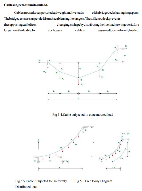
Consider a
cable as loaded in Fig.5.3. Let us assume that the cable lengths and sagat() are
known. The four reaction component sat ACDEB and B, cable
tensions in each of the four segments and three sag values: a total of eleven
unknown quantities are to be determined. From the geometry, one could write two
force equilibrium equations (0,0==??yxFF) at each
of the point and DCBA,,,Ei.e. a total of ten equations and the required
one more equation may be written from the geometry of the cable. For example, if
one of the sag is given then the problem can be solved easily. Otherwise if the
total length of the cable is given then the required equation may be written as
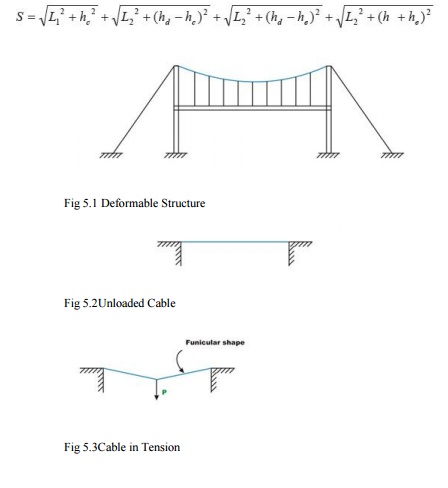
Fig
5.3Cable in Tension
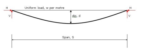
Cable subjected
to uniform load.
Cables are
used to support the dead weight and live loads of the bridge decks having long spans.
The bridge
decks are suspended from the cable using the hangers. The stiffened deck prevents
the supporting cable from changing its
shape by distributing the live load moving over it, for a longer length of cable.
In such cases cable is assumed to be uniformly loaded.
Consider a
cable which is uniformly loaded as shown in Fig 5.4.
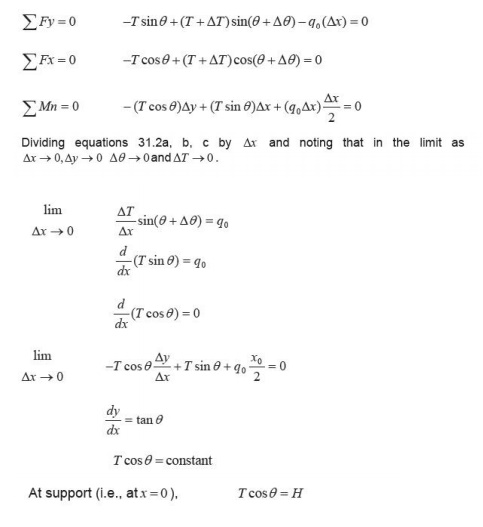
Due to uniformly distributed load,
the cable takes a parabolic shape. However due to its own dead weight it takes a
shape of acatenary. However dead weight of the cable is neglected in the
present analysis.
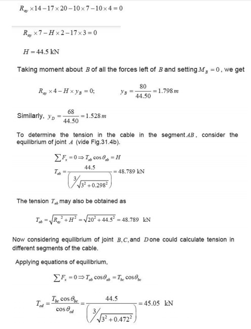
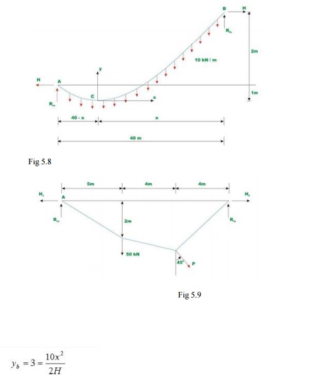
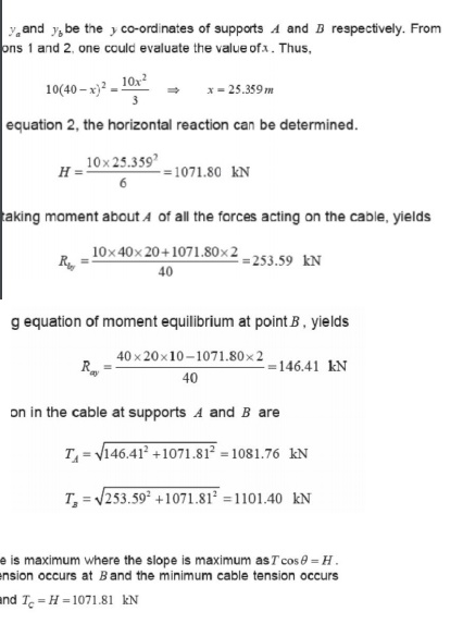
5.3. Example
Determine
reaction components at A and B, tension in the cable and the sag of the cable
shown inFig.5.7. Neglect the self weight of the cable in the analysis.
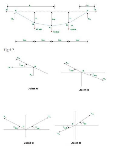
Since there
are no horizontal loads, horizontal reactions at A and B should be the same.
Taking moment about E, yields
CABLE AND SPACE STRUCTURES
1. What are cable structures?
Long span
structures subjected to tension and uses suspension cables for supports.
Examples of cable structures are suspension bridges, cable stayed roof.
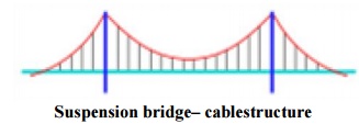
Suspension bridge- cable structure
2. What is the true shape of cable structures?
Cable structures especially the cable
of a suspension bridge is in the form of a catenary. Catenary is the shape assumed
by astring/cable freely suspended between two points.
3. What is the nature of force in the cables?
Cables of cable structures have only tension and no
compression or bending.
4. What is a catenary?
Catenary is the shape taken up by
a cable or rope freely suspended between two supports and under its own self weight.
5. Mention
the different types of cable structures.
Cable structures are mainly of two
types: (a) Cable over a guide pulley (b)Cable over a saddle
6. Briefly
explain cable over a guide pulley.
Cable over a guide pulley has the
following properties:
·
Tension in the suspension cable=Tension in the anchor
cable
·
The supporting tower will be subjected to vertical
pressure and bending due to net horizontal cable tension.
7. Briefly
explain cable over saddle.
Cable over saddle has the following
properties:
·
Horizontal component of tension in the suspension
cable=Horizontal component of tension in the anchor cable
·
The supporting tower will be subjected to only vertical
pressure due to cable tension.
8. What is
the degree of indeterminacy of a suspension bridge with two hinged
stiffening girder?
The two hinged stiffening girder has one degree of indeterminacy.
9. What are the main functions of stiffening
girders in suspension bridges?
Stiffening girders have the following functions.
·They help in keeping the cables
in shape
·They resist part of shear force and
bending moment due to live loads.
10.
Differentiate between planetruss and
spacetruss.
Planetruss
·
All members liein one plane
·
All joints are assumed to be hinged.
Spacetruss
·
This is a three dimensional truss
·
All joints are assumed to be ball and socketed.
11.
Define tension coefficient of a truss member.
The tension coefficient for a member
of a truss is defined as the pull or tension in the member divided by its
length, i. e. the force in the member per unit length.
12.
Give some examples of beams curved in plan.
Curved beams are found in the following
structures.
Beams in
a bridge negotiating a curve
·
Ring beams supporting a water tank
·
Beams supporting cornerlintels
·
Beams in ramps
13.
What are the forces developed in beams curved
in plan?
Beams curved in plan will have the
following forces developed in them:
·
Bending moments
·
Shear forces
·
Torsional moments
14.
What are the significant features of circular
beams on equally spaced supports?
·
Slope on either side of any support will be zero.
·
Torsional moment on every support will be zero
15.
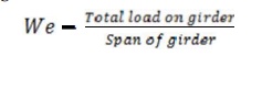
Give the expression for calculating
equivalent UDL on a girder.
Equivalent
UDL on a girder is given by We:
16.
Give the range of central dip of a cable.
The central dip of acablera nges
from 1/10 to 1/12 of the span.
17.
Give the horizontal and vertical components
of a cable structure subjected to UDL.
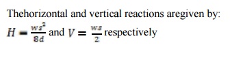
18. Give the expression for determining the tension
T in the cable.
The tension developed in the cable is given by
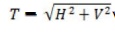
Where H=horizontal component and
V=vertical component.
19.
Give the types of significant cable structures
Linear structures
·
Suspension bridge s
·
Draped cables
·
Cable-stayed beams or trusses
·
Cable trusses
·
Straight tensioned cables
Three-dimensional structures
·
Bicycle wheel roof
·
3D cable trusses
·
Tensegrity structures
·
Tensairity structures
20.
What are cables made of?
Cables can be of mild steel, high
strength steel, stainless steel, or polyest er fibres. Structural cables are
made of a series of small strandstwistedor bound together to form a much larger
cable. Steel cables are either spiral strand, where circular rodsaretwisted
together or locked coil strand, where individual interlocking steel strands form
the cable (often with aspiral strand core).
Spiral strand is slightly weaker than locked coil strand.
Steel spiral strand cables have a Young's modulus, Eof150 ± 10kN/mm˛ and come in
sizes from 3 to 90 mm diameter. Spiral strand suffers from construction stretch,
where the strands compact when the cable is loaded.
Related Topics