Chapter: Mechanical : Dynamics of Machines : Balancing
Solved Problems: Dynamics of Machines - Balancing
SOLVED PROBLEMS
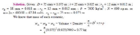
1. A shaft has three eccentrics,
each 75 mm diameter and 25 mm thick, machined in one piece with the shaft. The central planes of the eccentric
are 60 mm apart. The distance of the centres from the axis of rotation are 12
mm, 18 mm and 12 mm and their angular positions are 120° apart. The density of
metal is 7000 kg/m3. Find the amount of out-of-balance force and
couple at 600 r.p.m. If the shaft is balanced by adding two masses at a radius
75 mm and at distances of 100 mm from the central plane of the middle
eccentric, find the amount of the masses and their angular positions.
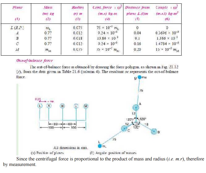
Let L and M be the planes at distances of 100 mm from the central plane of
middle eccentric. The position of the planes and the angular position of the
three eccentrics is shown in Fig. 21.12 (a)
and (b) respectively. Assuming L as the reference plane and mass of the
eccentric A in the vertical
direction, the data may be tabulated as below :
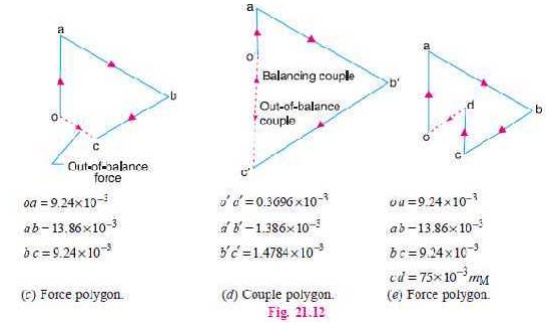
Out-of-balance force =
vector oc = 4.75 × 10⁻³
kg-m
= 4.75 × 10⁻³
× ω 2 = 4.75 × 10⁻³ (62.84)2
= 18.76 N Ans.
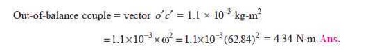
Out-of-balance
couple
The out-of-balance couple is
obtained by drawing the couple polygon from the data given in Table 21.6
(column 6), as shown in Fig. 21.12 (d). The resultant o ′ c′ represents the out-of- balance
couple. Since the couple is proportional to the product of force and distance
(m.r.l), there-fore by measurement,
Amount
of balancing masses and their angular positions
The vector c ′ o′ (in the direction from
c′ to o′ ), as shown in Fig.
21.12 (d) represents the balancing
couple and is proportional to 15 × 10–3 mM, i.e.
15 × 10–3 mM = vector c ′ o′ = 1.1
× 10–3 kg-m2
mM = 0.073 kg Ans.
Draw OM in Fig. 21.12 (b) parallel to vector c ′ o′ . By measurement, we find that the angular position of
balancing mass (mM) is 5°
from mass A in the clockwise
direction. Ans.
In order to find the
balancing mass (mL), a
force polygon as shown in Fig. 21.12 (e)
is drawn. The closing side of the polygon i.e.
vector do (in the direction from d to o)
represents the balancing force and is proportional to 75 × 10–3 mL. By measurement, we find
that,
75 × 10–3 mL = vector do = 5.2 × 10⁻³ kg-m or mL = 0.0693 kg Ans. Draw OL in Fig. 21.12
(b), parallel to vector do.
By measurement, we
find that the angular position of mass (mL)
is 124° from mass A in the clockwise
direction. Ans.
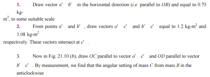
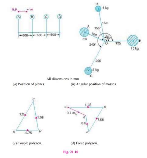
2.(i) A, B, C and D are four masses carried by a rotating shaft
at radii 100, 125, 200 and 150 mm respectively. The planes in which the masses
revolve are spaced 600 mm apart and the mass of B, C and D are 10 kg, 5 kg, and
4 kg respectively.Find the required mass A and the relative angular settings of
the four masses so that the shaft shall be in complete balance.
Solution. Given : rA = 100 mm = 0.1 m ; rB = 125 mm = 0.125 m ; rC = 200 mm = 0.2 m ; rD = 150 mm = 0.15 m ; mB = 10 kg ; mC = 5 kg ; mD = 4 kg
1. The
position of planes is shown in Fig. 21.10 (a).
Assuming the plane of mass A as the reference plane (R.P.),
the data may be tabulated as below :
First of all, the
angular setting of masses C and D is obtained by drawing the couple
polygon from the data given in Table 21.4 (column 6). Assume the position of
mass B in the horizontal direction OB as shown in Fig. 21.10 (b). Now the couple polygon as shown in
Fig.(c) is drawn as discussed below :
direction, i.e.
∠ BOC = 240° Ans.
and angular setting of mass D
from mass B in the anticlockwise
direction, i.e. ∠ BOD = 100°
Ans.
In order to find the
required mass A (mA) and its angular setting, draw the force polygon to
some suitable scale, as shown in Fig. 21.10 (d), from the data given in Table 21.4 (column 4).
Since the closing side of the force polygon (vector do) is proportional to 0.1 mA, therefore
by measurement,
0.1 m = 0.7 kg-m2 or mA= 7 kg Ans.
Now draw OA in Fig.
21.10 (b ), parallel to vector do. By measurement, we find that the
angular setting of mass A from mass B in the anticlockwise direction, i.e.
∠ BOA = 155° Ans.
2(ii)
Derives the expressions for the following: (i) Variation in tractive force and
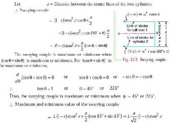
(ii) Swaying couple. (8) (AU-NOV/DEC-2009)
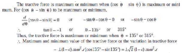
Variation in tractive force
The resultant unbalanced force due to the two cylinders, along
the line of stroke, is known as tractive force. Let the crank for the first cylinder be
inclined at an angle θ with the line of stroke, as shown in Fig. 22.4.
Since the crank for the second cylinder is at right angle to the
first crank, therefore the angle of inclination for the second crank will be
(90° + θ ).
Let m = Mass of the reciprocating parts per cylinder, and
c = Fraction of the
reciprocating parts to be balanced.
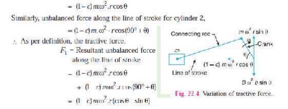
We know that
unbalanced force along the line of stroke for cylinder 1
The unbalanced forces
along the line of stroke for the two cylinders constitute a couple about the
centre line YY between the cylinders
as shown in Fig. 22.5.
This couple has
swaying effect about a vertical axis, and tends to sway the engine alternately
in clockwise and anticlockwise directions. Hence the couple is known as swaying couple.
a = Distance between the centre lines of the two cylinders.
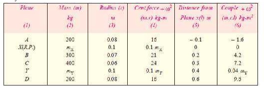
3. A shaft carries four masses
A, B, C and D of magnitude 200 kg, 300 kg, 400 kg and 200 kg respectively and revolving at radii 80 mm, 70 mm, 60
mm and 80 mm in planes measured from A at 300 mm, 400 mm and 700 mm. The angles
between the cranks measured anticlockwise are A to B 45°, B to C 70° and C to D
120°. The balancing masses are to be placed in planes X and Y. The distance
between the planes A and X is 100 mm, between X and Y is 400 mm and between Y
and D is 200 mm. If the balancing masses revolve at a radius of 100 mm, find
their magnitudes and angular positions.
Solution. Given : mA = 200 kg ; mB = 300 kg ; mC = 400 kg ; mD = 200 kg ; rA = 80 mm =0.08m
;
rB = 70 mm = 0.07 m ; rC = 60 mm = 0.06 m ; rD = 80 mm =
0.08 m ; rX =
rY = 100 mm = 0.1 m Let mX
= Balancing mass placed in plane X,
and mY = Balancing mass
placed in plane Y.
The position of planes
and angular position of the masses (assuming the mass A as horizontal) are
shown in Fig. 21.8 (a) and (b) respectively.
Assume the plane X as
the reference plane (R.P.). The
distances of the planes to the right of plane X are taken as + ve while the distances of the planes to the left
of plane X are taken as – ve. The
data may be tabulated as shown in Table 21.2.
The balancing masses mX
and mY and their angular
positions may be determined graphi-cally as discussed below :
1. First of all, draw the
couple polygon from the data given in Table 21.2 (column 6) as shown in Fig. 21.8 (c) to some
suitable scale. The vector d ′ o′ represents the balanced couple. Since the balanced couple is
proportional to 0.04 mY,
therefore by measurement,
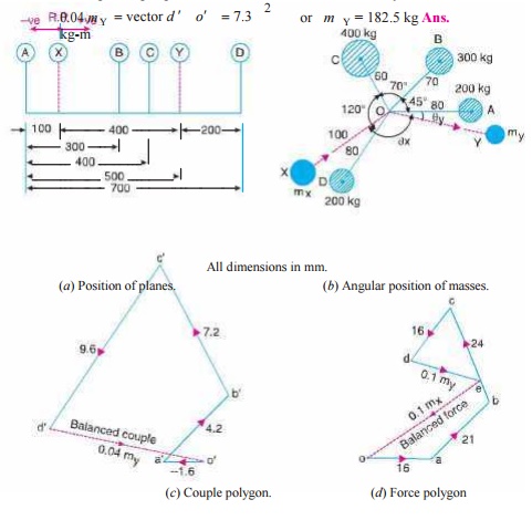
The angular position
of the mass mY is obtained
by drawing OmY in Fig.
21.8 (b), parallel to vector d ′ o′ . By measurement, the angular position of mY is θ Y = 12oin the clockwise
direction from mass mA
(i.e. 200 kg ). Ans.
2. Now
draw the force polygon from the data given in Table 21.2 (column 4) as shown in
Fig. 21.8 (d). The vector eo
represents the balanced force. Since the balanced force is proportional to 0.1 mX, therefore by measurement,
0.1 mX = vector eo = 35.5 kg-m or mX = 355 kg Ans.
The angular position
of the mass mX is obtained
by drawing OmX in Fig.
21.8 (b), parallel to vector eo. By measurement, the angular position
of mX is θ X = 145o in the clockwise direction from mass mA
(i.e. 200 kg ). Ans.
4.
Four masses A, B, C and D as shown below are to be completely balanced.
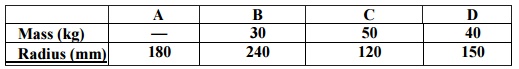
The planes containing masses B and C are 300 mm apart. The
angle between planes containing B and C is 90°. B and C make angles of 210° and
120° respectively with D in the same sense. Find :
1.
The magnitude and the angular
position of mass A ; and
2.
The position of planes A and D.
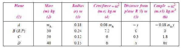
Solution. Given : rA = 180 mm = 0.18 m ; mB = 30 kg ; rB = 240 mm = 0.24 m ; mC = 50 kg ; rC = 120 mm = 0.12 m ; mD = 40 kg ; rD = 150 mm = 0.15 m ;
∠ BOC = 90° ; ∠ BOD = 210° ; ∠ COD = 120°
1. The magnitude and
the angular position of mass A
Let
mA = Magnitude of
Mass A,
x = Distance between the planes B and D, and y = Distance
between the planes A and B.
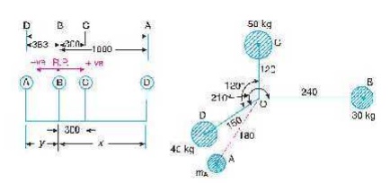
The position of the
planes and the angular position of the masses is shown in Fig. 21.9 (a) and (b) respectively.
Assuming the plane B as the reference plane (R.P.)
and the mass B (mB) along the horizon-tal line as shown in Fig. 21.9 (b), the data may be tabulated as below :
The magnitude and angular position
of mass A may be determined by
drawing the force polygon from the data given in Table 21.3 (Column 4), as
shown in Fig. 21.9 (c), to some
suitable scale. Since the masses are to be completely balanced, therefore the
force polygon must be a closed figure. The closing side (i.e. vector do) is
proportional to 0.18 mA.
By measurement,
0.18 mA = Vector do
= 3.6 kg-m or mA
= 20 kg Ans.
In order to find the angular
position of mass A, draw OA in Fig. 21.9 (b) parallel to vector do.
By measurement, we find that the angular position of mass A from mass B in the
anticlockwise direction is ∠ AOB =
236° Ans.
All dimensions in mm.
(c) Force polygon. (d) Couple
polygon.
Fig. 21.9.
![]()
![]()
![]()
![]()
![]()
2. Position of planes A
and D
The position of planes
A and D may be obtained by drawing the couple polygon, as shown in Fig.
21.9 (d), from the data given in
Table 21.3 (column 6). The couple polygon is drawn as discussed below :
1.Draw vector o′ c′
parallel to OC and equal to
1.8 kg-m2, to some suitable scale.
2.From points c′
and o′ , draw lines parallel to OD and OA respectively,
such that they intersect at point d′ . By measurement, we
find that
6 x = vector c′ d′ = 2.3 kg-m2 or x = 0.383 m
We see from the couple polygon that the direction of vector c ′ d′ is opposite to the
direction of mass D. Therefore the plane of mass D is 0.383 m or 383 mm towards left of
plane B and not towards right of
plane B as already assumed. Ans.
Again by measurement
from couple polygon,
– 0.18 mA.y = vector o′ d′ = 3.6 kg-m2
– 0.18 × 20 y = 3.6
or y = – 1 m
The negative sign
indicates that the plane A is not
towards left of B as assumed but it
is 1 m or 1000 mm towards right of plane B.
Ans.
5. An inside cylinder locomotive
has its cylinder centre lines 0.7 m apart and has a stroke of 0.6 m. The rotating masses per cylinder are equivalent
to 150 kg at the crank pin, and the reciprocating masses per cylinder to 180
kg. The wheel centre lines are 1.5 m apart. The cranks are at right angles.
The whole of the rotating and 2/3 of the
recipro-cating masses are to be balanced by masses placed at a radius of 0.6 m.
Find the magnitude and direction of the balancing masses.
Find the fluctuation in rail pressure under
one wheel, variation of tractive effort and the magnitude of swaying couple at
a crank speed of 300 r.p.m. (AU-NOV/DEC-2008)
Solution. Given : a = 0.7 m; lB = lC = 0.6 m or
rB = rC = 0.3 m; m1 = 150 kg; m2 = 180 kg; c = 2/3; rA =
rD = 0.6 m; N = 300 r.p.m. or ω 2 300 / 60 = 31.42 rad/s
We know that the
equivalent mass of the rotating parts to be balanced per cylinder at the crank
pin,
m = mB =
mC = m1 + c.m2 = 150 + 2/3 × 180 = 270 kg
![]()
Magnitude and direction of the
balancing masses
Let mA and mD
= Magnitude of the balancing masses
θ A
and θ
D = Angular position of the balancing masses mA and mD from the first crank B.
The
magnitude and direction of the balancing masses may be determined graphically
as discussed below :
1. First of all, draw the space diagram
to show the positions of the planes of the wheels and the cylinders, as shown
in Fig. 22.7 (a). Since the cranks of
the cylinders are at right angles, therefore assuming the position of crank of
the cylinder B in the horizontal
direc-tion, draw OC and OB at right angles to each other as
shown in Fig. 22.7 (b).
Tabulate the data as
given in the following table. Assume the plane of wheel A as the reference plane.
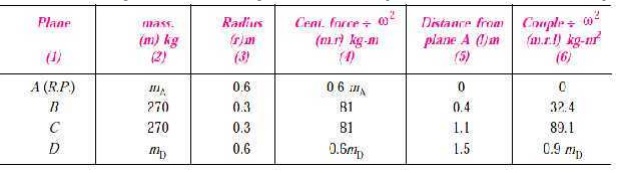
3.
Now, draw the couple polygon from
the data given in Table 22.1 (column
6), to some suitable
scale, as shown in Fig 22.7 (c). The closing side c ′o′
represents the balancing couple and it is proportional to 0.9 mD. Therefore, by
measurement,
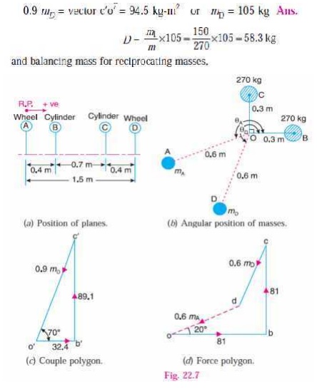
4. To determine the
angular position of the balancing mass D, draw OD in Fig. 22.7 (b) parallel to vector c ′ o′ . By measurement,
θ
D = 250°
Ans.
5.
In order to find the balancing mass A, draw the force polygon from the data given in
Table 22.1 (column 4),
to some suitable scale, as shown in Fig. 22.7 (d), The vector do
represents the balancing force and it is proportional to 0.6 mA. Therefore by measurement,
0.6
mA = vector do = 63 kg-m
or mA = 105 kg Ans.
6. To determine the
angular position of the balancing mass A,
draw OA in Fig. 22.7 (b) parallel to vector do. By measurement,
θ
A = 200°
Ans.
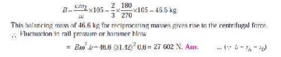
Fluctuation in rail pressure
We know that each balancing mass105
kg
∴ Balancing mass
for rotating masses,
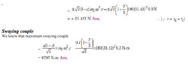
Variation of tractive effort
We know that maximum variation of tractive
effort
6.
The following data apply to an outside cylinder
uncoupled locomotive :
Mass of rotating parts per cylinder = 360 kg ; Mass of
reciprocating parts per cylinder = 300 kg ; Angle between cranks = 90° ; Crank
radius = 0.3 m ; Cylinder centres = 1.75 m ; Radius of balance masses = 0.75 m
; Wheel centres = 1.45 m. If whole of the rotating and two-thirds of
reciprocating parts are to be balanced in planes of the driving wheels, find :
1.
Magnitude and angular positions of
balance masses,
2.
Speed in kilometres per hour at
which the wheel will lift off the rails when the load on each driving wheel is
30 kN and the diameter of tread of driving wheels is 1.8 m, and
3. Swaying couple at speed arrived
at in (2) above.
Solution : Given : m1 = 360 kg ; m2 = 300 kg ; ∠ AOD = 90° ; rA = rD = 0.3 m ; a = 1.75 m ; rB = rC
= 0.75 m ; c = 2 / 3.
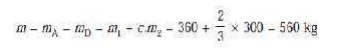
We know that the equivalent mass of
the rotating parts to be balanced per cylinder,
1.
Magnitude and angular position of balance
masses
Let mB and
mC = Magnitude of the
balance masses, and θB and θ
C = angular position of the balance masses mB and mC
from the crank A.
The magnitude and direction of the
balance masses may be determined, graphically, as discussed below :
First of all, draw the positions of
the planes of the wheels and the cylinders as shown in Fig. 22.11 (a). Since the cranks of the two
cylinders are at right angles, therefore assum-ing the position of the cylinder
A in the horizontal direction, draw OA and OD at right angles to each other as shown in Fig. 22.11 (b).
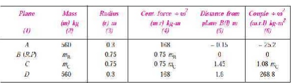
2.
Assuming the plane of wheel B as the reference plane, the data may
be tabulated as be-low:
3.
Now draw the couple polygon with the data given
in Table 22.4 column (6), to some
suitable scale as shown in Fig. 22.11(c). The closing side d ′ o′ represents
thebalancing couple and it is proportional to 1.08 mC. Therefore, by measurement,
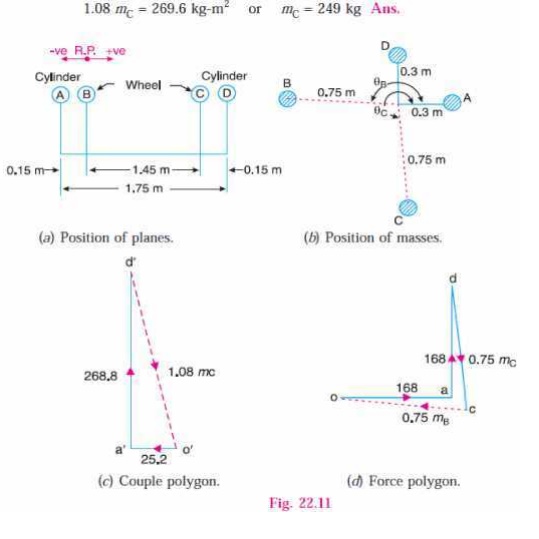
4. To determine the
angular position of the balancing mass
C, draw OC parallel to vector d′ o′ as shown in Fig. 22.11 (b). By measurement, θ C = 275° Ans.
5. In order to find the
balancing mass B, draw the force
polygon with the data given in Tablecolumn (4), to some suitable scale, as
shown in Fig. 22.11 (d). The vector co represents
the balancing force
and it is proportional to 0.75 mB.
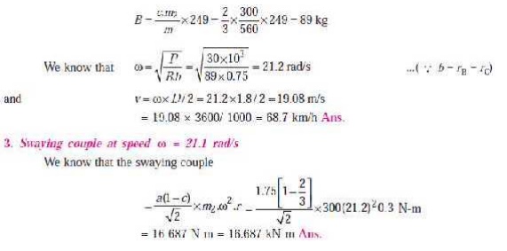
Therefore, by measurement, 0.75 mB = 186.75 kg-m or mB = 249 kg Ans.
4.
To
determine the angular position of the balancing mass B, draw OB parallel to
vector oc as shown Fig. 22.11 (b). By measurement, θ B =
174.5° Ans.
2.
Speed at which the wheel will lift off
the rails
Given : P = 30 kN = 30 ×
103 N ; D = 1.8 m
Let ω = Angular speed at
which the wheels will lift off the rails in rad/s, and v = Corresponding linear speed in km/h.
We know that each
balancing mass, mB = mC = 249 kg
∴ Balancing mass for reciprocating parts,
7. The three cranks
of a three cylinder locomotive are all on the same axle and are set at 120°.
The pitch of the cylinders is 1 meter and the stroke of each piston is 0.6 m.
The reciprocating masses are 300 kg for
inside cylinder and 260 kg for each outside cylinder and the planes of rotation
of the balance masses are 0.8 m from the inside crank. If 40% of the
reciprocating parts are to be balanced, find :
1. the magnitude and the position of the balancing masses
required at a radius of 0.6 m ;
And
2. the hammer blow
per wheel when the axle makes 6 r.p.s.
Solution. Given : ∠ AOB =
∠ BOC = ∠ COA = 120° ; lA = lB = lC = 0.6 m or rA = rB
= rC = 0.3 m ; mI = 300 kg ; mO = 260 kg ; c = 40% = 0.4 ; b1 = b2 = 0.6 m ; N = 6 r.p.s.
= 6 × 2 π = 37.7 rad/s
Since 40% of the reciprocating
masses are to be balanced, therefore mass of the reciprocat-ing parts to be
balanced for each outside cylinder,
mA
=
mC = c ×
mO = 0.4 × 260 = 104
kg and mass of the reciprocating
parts to be balanced for inside cylinder,
mB
=
c × m1 = 0.4 × 300 = 120 kg
1.
Magnitude and position of the balancing
masses
Let B1 and
B2 = Magnitude of the
balancing masses
in kg,
θ1
and θ2 = Angular
position of the balancing masses B1
and B2
from crank A.
The magnitude and
position of the balancing masses may be determined graphically as discussed
below :
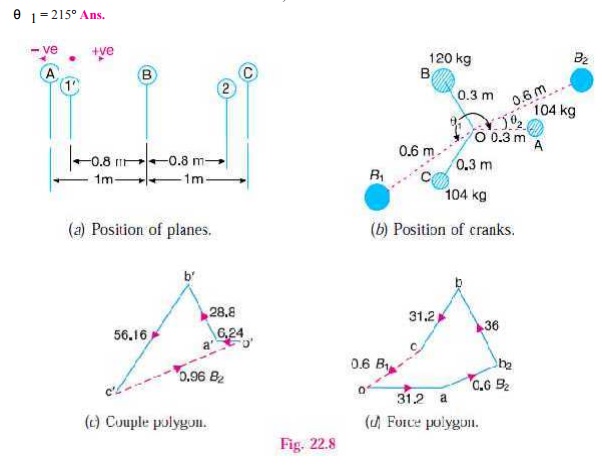
1. First of all, draw the position of
planes and cranks as shown in Fig. 22.8 (a)
and (b) respectively. The position of
crank A is assumed in the horizontal
direction.
Tabulate the data as given in the
following table. Assume the plane of balancing mass B1 (i.e. plane 1) as the reference plane.
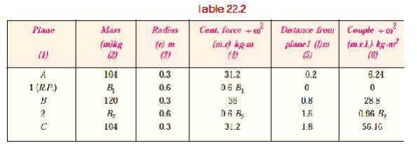
3. Now draw the couple
polygon with the data given in Table 22.2 (column 6), to some suitable scale, as shown in Fig. 22.8 (c). The closing side c ′ o′ represents the balancing couple
and it is proportional
to 0.96 B2. Therefore, by
measurement,
0.96 B2 = vector c ′ o′ = 55.2 kg-m2 or B2 = 57.5 kg Ans.
4.
To determine the angular position of the balancing mass B2, draw OB2 parallel to vector c
′
o′ as shown in Fig. 22.8
(b). By measurement,
θ2= 24° Ans.
5.
In order to find the balance mass B1, draw the force polygon with the data given in Table
22.2(column 4 ), to some suitable scale, as shown in Fig. 22.8 (d). The closing side co represents the balancing force and it
is proportional to 0.6 B1.
Therefore, by measurement,
0.6B1 = vector co = 34.5
kg-m or B1 = 57.5 kg Ans.
6.To determine the
angular position of the balancing mass B1,
draw OB1 parallel to
vector co, as shown in Fig. 22.8 (b). By measurement, θ1 = 215° Ans.
2.
Hammer blow per wheel
We know that hammer blow per wheel
=
B1.ω 2.b1 = 57.5 (37.7)2 20.6 = 49 035 N Ans.
8.
The following data refer to two cylinder locomotive
with cranks at 90° :
Reciprocating mass per cylinder = 300 kg ; Crank radius = 0.3 m
; Driving wheel diameter = 1.8 m ; Distance between cylinder centre lines =
0.65 m ; Distance between the driving wheel central planes = 1.55 m.
Determine : 1. the fraction of the reciprocating masses to be balanced, if the
hammer blow is not to exceed 46 kN at 96.5 km. p.h. ; 2. the variation in
tractive effort ; and 3. the maximum swaying couple
Solution. Given : m = 300 kg ; r
= 0.3 m ; D = 1.8 m or R = 0.9 m ; a = 0.65 m ; Hammer blow =
46 kN = 46 × 103 N ; v =
96.5 km/h = 26.8 m/s
1. Fraction of the
reciprocating masses to be balanced
Let
c = Fraction of the reciprocating
masses to be balanced, and
B = Magnitude of balancing mass placed at each of the driving
wheels at radius b. We know that the mass of the
reciprocating parts to be balanced = c.m
= 300c kg
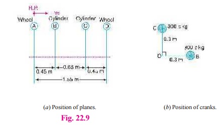
Fig. 22.9
The position of planes
of the wheels and cylinders is shown in Fig. 22.9 (a), and the position of
cranks is shown in Fig
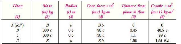
22.9 (b). Assuming the plane of wheel
A as the reference plane, the data
may be tabulated as below :
Now the couple polygon, to some suitable scale, may be drawn
with the data given in Table 22.3 (column 6), as shown in Fig. 22.10. The
closing side of the polygon (vector c′ o′
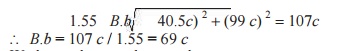
) represents the balancing couple and is proportional to 1.55 B.b.
From the couple polygon,
We know that angular
speed,
ω = v/R
= 26.8/0.9 = 29.8 rad/s ∴ Hammer
blow,
46 × 103 = B. ω 2 .b
= 69 c (29.8)2 = 61 275 c
∴
c = 46 × 103/61
275 = 0.751
Ans.
2. Variation in tractive effort
We know that variation in tractive
effort,
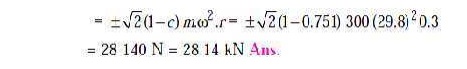
3.Maximum swaying couple
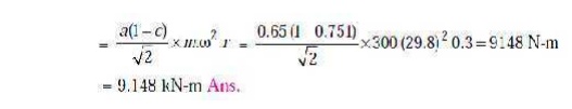
TUTORIAL
PROBLEMS:
1.
Four
masses A, B, C and D revolve at equal radii and are equally
spaced along a shaft. The mass B is 7
kg and the radii of C and D make angles of 90° and 240°
respectively with the radius of B.
Find the magnitude of the masses A, C and D and the angular position of A
so that the system may be completely balanced.
[Ans. 5 kg ; 6 kg ; 4.67 kg ; 205° from mass B in anticlockwise direction]
2. A rotating shaft carries four masses
A, B, C and D
which are radially attached to it. The mass centres are 30 mm, 38 mm, 40 mm and 35 mm respectively from the axis of
rotation. The masses A, C and D are 7.5 kg, 5 kg and 4 kg respectively. The axial distances
between the planes of rotation of A
and B is 400 mm and between B and C is 500 mm. The masses A
and C are at right angles to each
other. Find for a complete balance,
1. the angles between the masses B and D from mass A,
2. the axial distance between the planes of
rotation of C and D,
3. the magnitude of mass B.[Ans. 162.5°, 47.5° ; 511
mm : 9.24 kg]
3.
A
three cylinder radial engine driven by a common crank has the cylinders spaced
at 120°. The stroke is 125 mm, length of the connecting rod 225 mm and the mass
of the reciprocating parts per cylinder 2 kg. Calculate the primary and
secondary forces at crank shaft speed of 1200 r.p.m.
[Ans.
3000 N ; 830 N]
4.
The
pistons of a 60° twin V-engine has
strokes of 120 mm. The connecting rods driving a common crank has a length of
200 mm. The mass of the reciprocating parts per cylinder is 1 kg and the
speed of the crank shaft is 2500
r.p.m. Determine the magnitude of the primary and secondary forces. [Ans.
6.3
kN ; 1.1 kN]
5.
A
twin cylinder V-engine has the
cylinders set at an angle of 45°, with both pistons connected to the single
crank. The crank radius is 62.5 mm and the connecting rods are 275 mm long. The
reciprocating mass per line is 1.5 kg and the total rotating mass is equivalent
to 2 kg at the crank radius. A balance mass fitted opposite to the crank, is
equivalent to 2.25 kg at a radius of 87.5 mm. Determine for an engine speed of
1800 r.p.m. ; the maximum and minimum values of the primary and secondary
forces due to the inertia of reciprocating and rotating masses.
[
Ans. Primary forces : 3240 N (max.) and 1830 N (min.) Secondary forces : 1020 N
(max.) and 470 N (min.)]
Related Topics