Chapter: Civil : Strength of Materials : Energy Principles
Solved Problems: Civil - Strength of Materials - Energy Principles
Calculate the central deflection and the slope at ends of a simply supported beam carrying a UDL w/ unit length over the whole span.
Solution:
a) Central deflection:
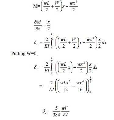
Since no point load is acting at the center where the deflection is required, apply the fictitious load W, then the reaction at A and

Consider a section at a distance x from A.
Bending moment at x,
b) Slope at ends
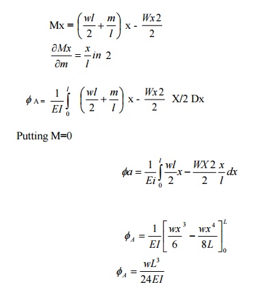
To obtain the slope at the end A, say apply a frictions moment A as shown in fig. The reactions at A and B will be

Where Mx is the moment at a point distant x from the origin (ie, B) is a function of M.
A beam AB of span 3mis fixed at both the ends and carries a point load of 9 KN at C distant 1m from A. The M.O.I. of the portion AC of the beam is 2I and that of portion CB is I. calculate the fixed end moments and reactions.
Solution:
There are four unknowns Ma, Ra, Mb and Rb.Only two equations of static are available (ie) åv =0 and åM =0
This problem is of second degree indeterminacy.
First choose MA and MB as redundant.
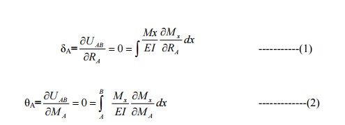
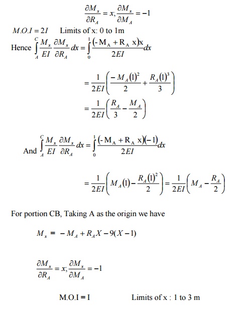
1) For portion AC:
Taking A as the origin
Mx = -MA + RA x
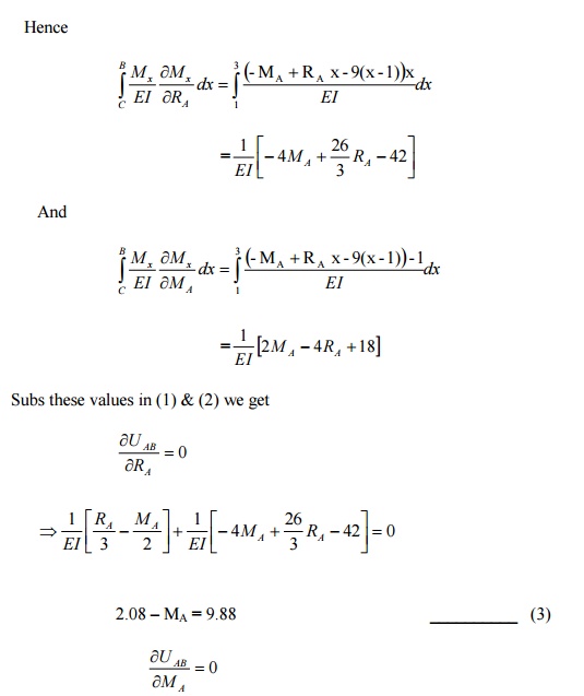
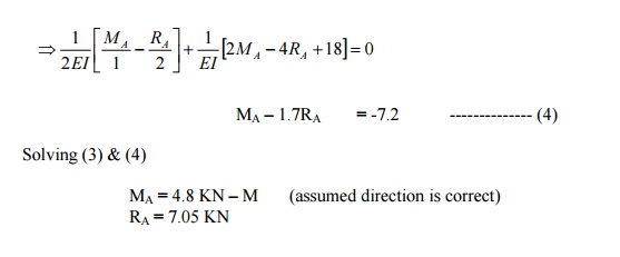
To find MB, take moments at B, and apply the condition åM =0 there. Taking clockwise moment as positive and anticlockwise moment as negative. Taking MB clockwise, we have
MB -MA =RA (3) -9x2 = 0
MB -4.8 + (7.05x 3) -18 = 0
MB = 1.65 KN -m (assumed direction is correct)
To find RB Apply åV =0 for the whole frame.
RB = 9 -RA = 9-7.05 = 1.95 KN
Using Castigliano's First Theorem,rotationofthe determine overhanging end A of the beam loaded.
Sol:
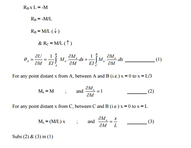
Rotation of A:
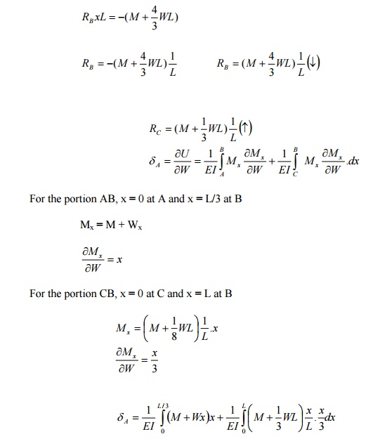
RB x L = -M
RB = -M/L
RB = M/L ( ¯)
& RC = M/L ( )
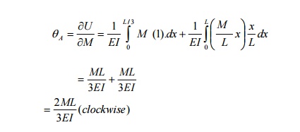
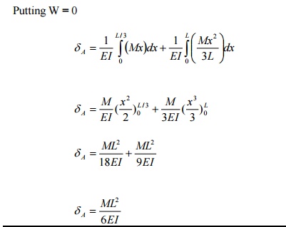
b) Deflection of A:
To find the deflection at A, apply a fictitious load W at A, in upward direction as
shown in fig.
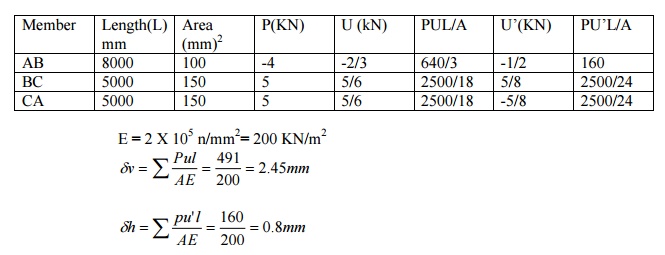
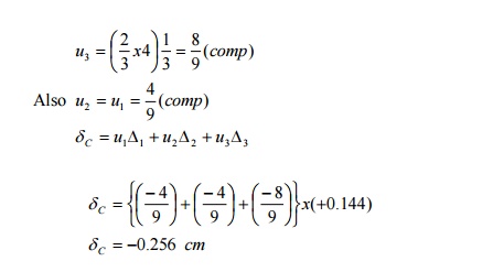
Determine the vertical and horizontal displacements of the point C of the pin-jointed frame shown in fig. The cross sectional area of AB is 100 sqmm and of AC and BC 150 mm2 each. E= 2 x 10 5 N/mm2. (By unit load method)
Sol:
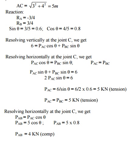
The vertical and horizontal deflections of the joint C are given by

A) Stresses due to External Loading:
B) Stresses due to unit vertical load at C:
Apply unit vertical load at C. The Stresses in each member will be 1/6 than of those obtained due to external load.

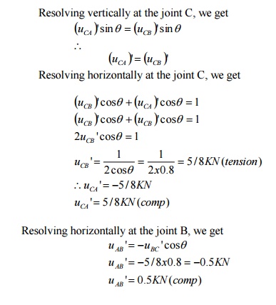
C) Stresses due to unit horizontal load at C:
Assume the horizontal load towards left as shown in fig.
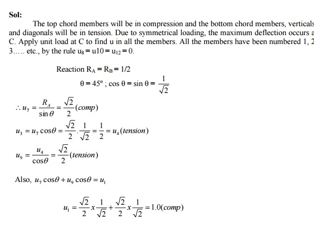
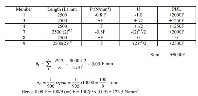
The frame shown in fig. Consists of four panels each 25m wide, and the cross sectional areas of the member are such that, when the frame carries equal loads at the panel points of the lower chord, the stress in all the tension members is f n/mm2 and the stress in all the comparison members of 0.8 f N/mm2.Determine the values of f if the ratio of the maximum deflection to span is 1/900 Take E= 2.0 x 10⁵ N/mm2.
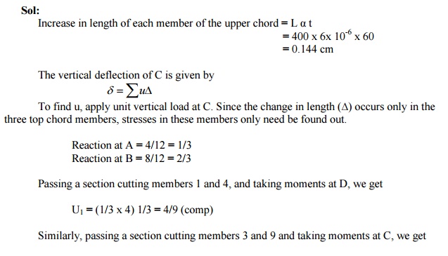
Determine the vertical deflection of the joint C of the frame shown in fig. due to temperature rise of 60º F in the upper chords only. The coefficient of expansion = 6.0 x 10⁻⁶ per 1º F and E = 2 x 10 6 kg /cm2.
Using the principle of least work, analyze the portal frame shown in Fig. Also plot the
B.M.D.
Sol:
The support is hinged. Since there are two equations at each supports. They are HA, VA, HD, and VD. The available equilibrium equation is three. (i.e.) åM =0, åH =0, åV =0 .
\ The structure is statically indeterminate to first degree. Let us treat the horizontal H ( ¬) at A as redundant. The horizontal reaction at D will evidently be = (3-H) ( ¬). By taking moments at D, we get
(VA x 3) + H (3-2) + (3 x 1) (2 -1.5) -(6 x 2) = 0
VA = 3.5 -H/3
VD = 6 -VA = 2.5 + H/3
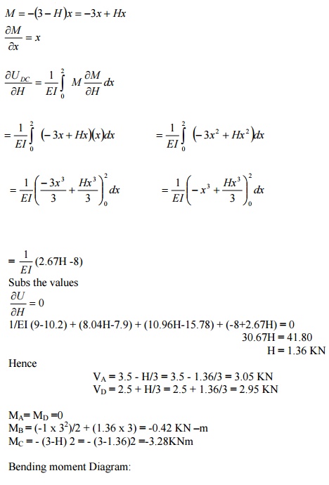
By the theorem of minimum strain energy,
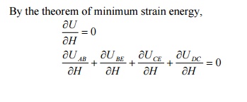
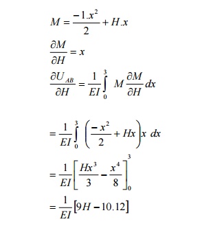
(1)For member AB:
Taking A as the origin.
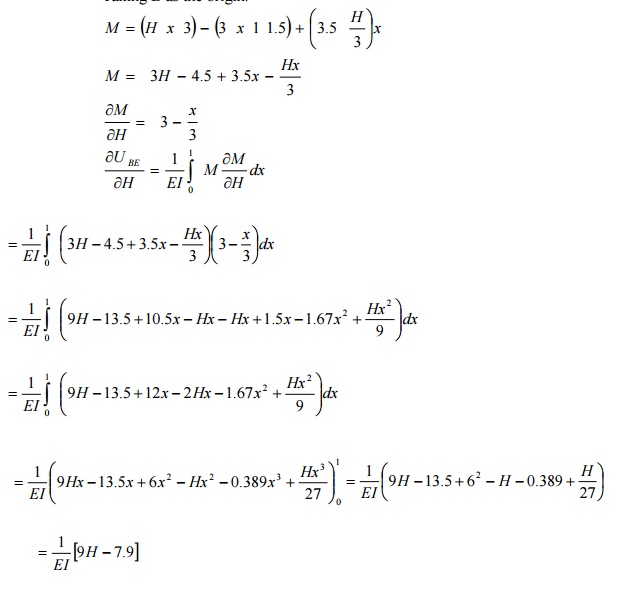
(2) For the member BE:
Taking B as the origin.
(3) For the member CE:
Taking C as the origin
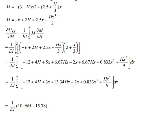
(4) For the member DC:
Taking D as the origin
A simply supported beam of span 6m is subjected to a concentrated load of 45 KN at 2m from the left support. Calculate the deflection under the load point. Take E = 200 x 106 KN/m2 and I = 14 x 10-6 m4.
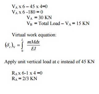
RB = Total load -RA = 1/3 KN
Virtual Moment:
Consider section between AC
M1 = 2/3 X1 [limit 0 to 2]
Section between CB
M2 = 2/3 X2-1 (X2-2 ) [limit 2 to 6 ]
Real Moment:
The internal moment due to given loading
M1= 30 x X1
M2 = 30 x X2 -45 (X2 -2)
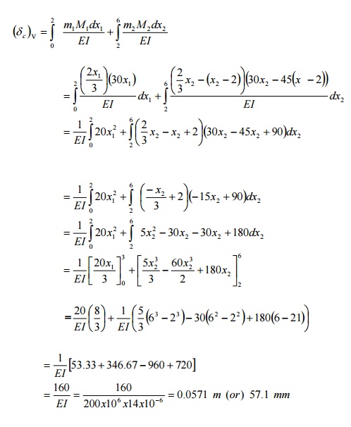
The deflection under the load = 57.1 mm
Define and prove the Maxwell's reciprocal theorem
The Maxwell?s reciprocal 'The work theorem done stated by the asf due to displacements caused by a second system of loads equals the work done by the second system of loads due to displacements caused by the first system o loads".
Maxwell?s theorem of reciprocal deflection has the following three versions:
1. The deflection at A due to unit force at B is equal to deflection at B due to unit force at A.
?AB = ?BA
2. The slope at A due to unit couple at B is equal to the slope at B due to unit couple A
?AB = ?BA
3. The slope at A due to unit load at B is equal to deflection at B due to unit couple.

Proof:
By unit load method,

Where,
M= bending moment at any point x due to external load.
m= bending moment at any point x due to unit load applied at the point where deflection is required.
Let mXA=bending moment at any point x due to unit load at A
Let mXB = bending moment at any point x due to unit load at B.
When unit load (external load) is applied at A,
M=mXA
To find deflection at B due to unit load at A, apply unit load at B.Then m= mXB
Hence,

Similarly,
When unit load (external load) is applied at B, M=mXB
To find the deflection at A due to unit load at B, apply unit load at A.then m= mXA

Comparing (i) & (ii) we get
?AB = BA?
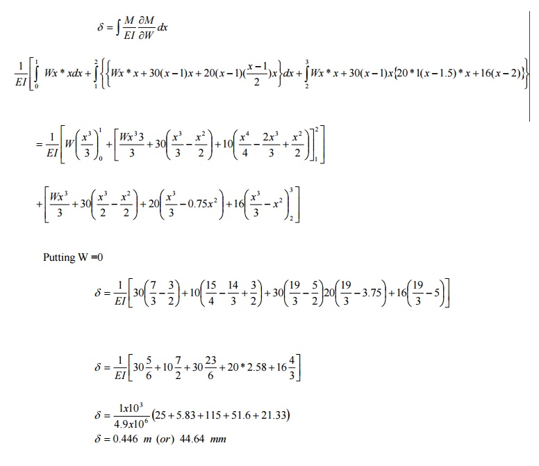
Using Castigliano's theorem, determine the de shown in the fig. Take EI = 4.9 MN/m2.
Solution:
Apply dummy load W at B. Since we have to determine the deflection of the free end. Consider a section xx at a distance x from B. Then
M x =Wx +30(x-1)+20 *1* (x-1.5)+16(x-2)
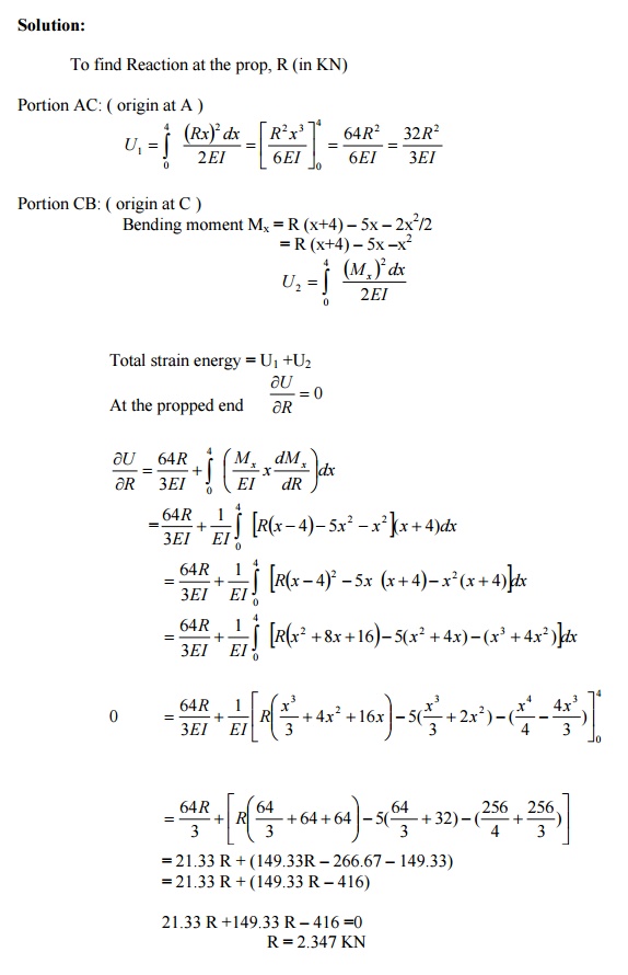
A cantilever, 8m long, carrying a point loads 5 KN at the center and an udl of 2 KN/m for a length 4m from the end B. If EI is the flexural rigidity of the cantilever find the reaction at the prop.
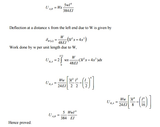
' A simply supported beam of span L is carrying a concentrated load W at the centre and a uniformly distributed load of intensity of w per unit leng the centre of the beam.
Solution:
Let the load W is applied first and then the uniformly distributed load w.
Deflection due to load W at the centre of the beam is given by

Hence work done by W due to w is given by:
Related Topics