Chapter: Embedded and Real Time Systems : Case Study
Software Modem
Software Modem:
Low-cost
modems generally use specialized chips, but some PCs implement the modem
functions in software. Before jumping into the modem design itself, we discuss
principles of how to transmit digital data over a telephone line. We will then
go through a specification and discuss architecture, module design, and
testing.
1. Theory of Operation and
Requirements
The modem
will use frequency-shift keying (FSK),a technique used in 1200-baud
modems. Keying alludes to Morse code—style keying. As shown in Figure 5.10, the
FSK scheme transmits sinusoidal tones, with 0 and 1 assigned to different
frequencies.
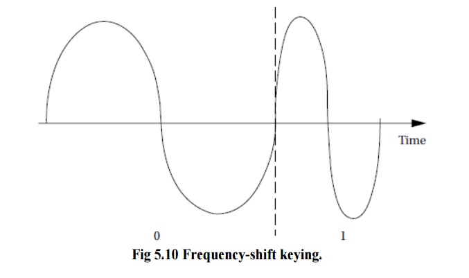
Sinusoidal
tones are much better suited to transmission over analog phone lines than are
the traditional high and low voltages of digital circuits. The 01 bit patterns
create the chirping sound characteristic of modems. (Higher-speed modems are
backward compatible with the 1200-baud FSK scheme and begin a transmission with
a protocol to determine which speed and protocol should be used.)
The
scheme used to translate the audio input into a bit stream is illustrated in
Figure 5.11.The analog input is sampled and the resulting stream is sent to two
digital filters (such as an FIR filter).
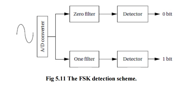
One
filter passes frequencies in the range that represents a 0 and rejects the
1-band frequencies, and the other filter does the converse.
The
outputs of the filters are sent to detectors, which compute the average value
of the signal over the past n
samples. When the energy goes above a threshold value, the appropriate bit is
detected.
We will
send data in units of 8-bit bytes. The transmitting and receiving modems agree
in advance on the length of time during which a bit will be transmitted
(otherwise known as the baud rate). But the transmitter and receiver are
physically separated and therefore are not synchronized in any way.
The
receiving modem does not know when the transmitter has started to send a byte.
Furthermore, even when the receiver does detect a transmission, the clock rates
of the transmitter and receiver may vary somewhat, causing them to fall out of
sync. In both cases, we can reduce the chances for error by sending the
waveforms for a longer time.
The
receiving process is illustrated in Figure 5.12. The receiver will detect the
start of a byte by looking for a start bit, which is always 0.
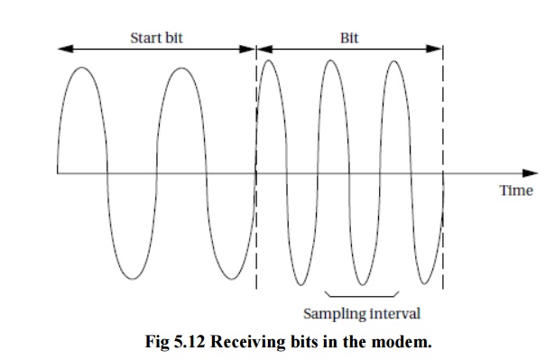
By
measuring the length of the start bit, the receiver knows where to look for the
start of the first bit. However, since the receiver may have slightly misjudged
the start of the bit, it does not immediately try to detect the bit.
The modem
will not implement a hardware interface to a telephone line or software for
dialing a phone number. We will assume that we have analog audio inputs and
outputs for sending and receiving. We will also run at a much slower bit rate
than 1200 baud to simplify the implementation.
Next, we
will not implement a serial interface to a host, but rather put the
transmitter’s message in memory and save the receiver’s result in memory as
well. Given those understandings, let’s fill out the requirements table.
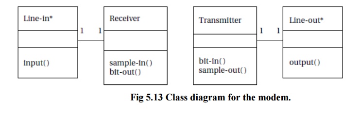
2. Specification
The basic
classes for the modem are shown in Figure 5.13.
3. System Architecture
The modem
consists of one small subsystem (the interrupt handlers for the samples) and
two major subsystems (transmitter and receiver).
Two
sample interrupt handlers are required, one for input and another for output,
but they are very simple. The transmitter is simpler, so let’s consider its
software architecture first.
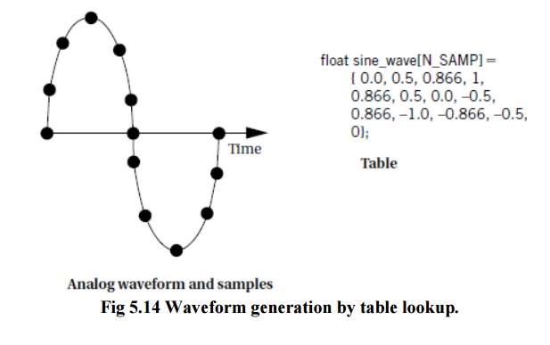
The best
way to generate waveforms that retain the proper shape over long intervals is table
lookup.
Software oscillators can be used to generate periodic signals, but numerical
problems limit their accuracy.
Figure
5.14 shows an analog waveform with sample points and the C code for these
samples. Table lookup can be combined with interpolation to generate
high-resolution waveforms without excessive memory costs, which is more
accurate than oscillators because no feedback is involved.
The
required number of samples for the modem can be found by experimentation with
the analog/digital converter and the sampling code.
The
structure of the receiver is considerably more complex. The filters and
detectors of Figure 5.12 can be implemented with circular buffers. But that
module must feed a state machine that recognizes the bits.
The
recognizer state machine must use a timer to determine when to start and stop
computing the filter output average based on the starting point of the bit. It
must then determine the nature of the bit at the proper interval. It must also
detect the start bit and measure it using the counter.
The
receiver sample interrupt handler is a natural candidate to double as the
receiver timer since the receiver’s time points are relative to samples.
The
hardware architecture is relatively simple. In addition to the analog/digital
and digital/analog converters, a timer is required. The amount of memory
required to implement the algorithms is relatively small.
Related Topics