Chapter: Solid State Drives : Synchronous Motor Drives
Self-Control Synchronous Motor
Self-Control Synchronous Motor
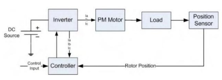
Control of PM motors is performed using field oriented control for the operation of synchronous motor as a dc motor. The stator windings of the motor are fed by an inverter that generates a variable frequency variable voltage. Instead of controlling the inverter frequency independently, the frequency and phase of the output wave are controlled using a position sensor as shown in figure.
Field oriented control was invented in the beginning of 1970s and it demonstrates that an induction motor or synchronous motor could be controlled like a separately excited dc motor by the orientation of the stator mmf or current vector in relation to the rotor flux to achieve a desired objective. In order for the motor to behave like DC motor, the control needs knowledge of the position of the instantaneous rotor flux or rotor position of permanent magnet motor. This needs a resolver or an absolute optical encoder. Knowing the position, the three phase currents can be calculated. Its calculation using the current matrix depends on the control desired. Some control options are constant torque and flux weakening. These options are based in the physical limitation of the motor and the inverter. The limit is established by the rated speed of the motor.
Field Oriented Control of PM Motors:
The PMSM control is equivalent to that of the dc motor by a decoupling control known as field oriented control or vector control. The vector control separates the torque component of current and flux channels in the motor through its stator excitation.
The vector control of the PM synchronous motor is derived from its dynamic model. Considering the currents as inputs, the three currents are:
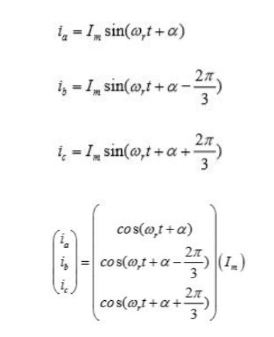
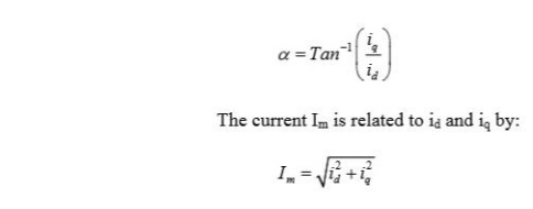
Where α is the angle between the rotor field and stator current phasor, r ω is the electrical rotor speed
The previous currents obtained are the stator currents that must be transformed to the rotor reference frame with the rotor speed r ω, using Park’s transformation. The q and d axis currents are constants in the rotor reference frames since α is a constant for a given load torque. As these constants, they are similar to the armature and field currents in the separately excited dc machine. The q axis current is distinctly equivalent to the armature current of the dc machine; the d axis current is field current, but not in its entirety. It is only a partial field current; the other part is contributed by the equivalent current source representing the permanent magnet field. For this reason the q axis current is called the torque producing component of the stator current and the d axis current is called the flux producing component of the stator current.
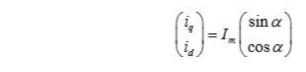
Substituting equation above and obtain id and iq in terms of Im as follows
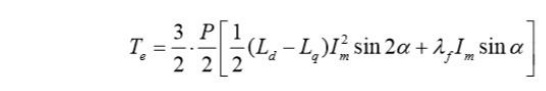
Using equations the electromagnetic torque equation is obtained as given below.
Constant Torque Operation:
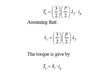
Constant torque control strategy is derived from field oriented control, where the maximum possible torque is desired at all times like the dc motor. This is performed by making the torque producing current iq equal to the supply current Im. That results in selecting the α angle to be 90 º degrees according to equation. By making the id current equal to zero the torque equation can be rewritten as:
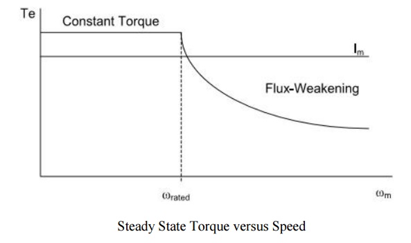
Flux-weakening:
Flux weakening is the process of reducing the flux in the d axis direction of the motor which results in an increased speed range.
The motor drive is operated with rated flux linkages up to a speed where the ratio between the induced emf and stator frequency (V/f) is maintained constant. After the base frequency, the V/f ratio is reduced due to the limit of the inverter dc voltage source which is fixed. The weakening of the field flux is required for operation above the base frequency.
This reduces the V/f ratio. This operation results in a reduction of the torque proportional to a change in the frequency and the motor operates in the constant power region.
The rotor flux of PMSM is generated by permanent magnet which cannot be directly reduced as induction motor. The principle of flux-weakening control of PMSM is to increase negative direct axis current and use armature reaction to reduce air gap flux, which equivalently reduces flux and achieves the purpose of flux-weakening control.
This method changes torque by altering the angle between the stator MMF and the rotor d axis. In
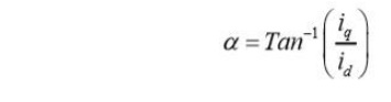
the flux weakening region where ωr > ωrated angle α is controlled by proper control of id and iq for the same value of stator current. Since iq is reduced the output torque is also reduced. The angle α can be obtained as:
Flux-weakening control realization
The realization process of equivalent flux-weakening control is as follows,
1) Measuring rotor position and speed ωr from a sensor which is set in motor rotation axis.
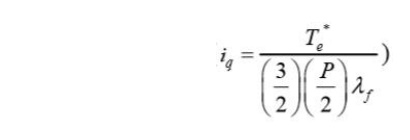
2) The motor at the flux weakening region with a speed loop, Te* is obtained from the PI controller.
3) Calculate Iq*
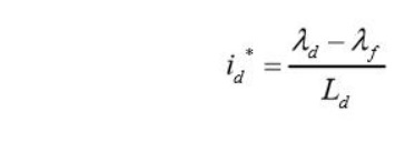
4) Calculate Id* using equation:
5) Then the current controller makes uses of the reference signals to control the inverter for the desired output currents.
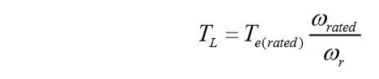
6) The load torque is adjust to the maximum available torque for the reference speed
Related Topics