Chapter: Solid State Drives : Synchronous Motor Drives
Design Equations of Boost Power Factor Correction Circuit
The AC input voltage given to the power factor correction circuit is 100V and input frequency is 50Hz.
DESIGN EQUATIONS OF BOOST POWER
FACTOR CORRECTION CIRCUIT
The AC
input voltage given to the power factor correction circuit is 100V and input
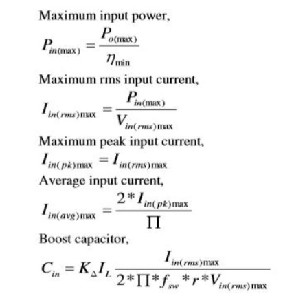
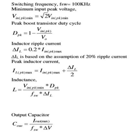
frequency is 50Hz. The selection of boost converter components is based on the
following equations Maximum input power,
Study Material, Lecturing Notes, Assignment, Reference, Wiki description explanation, brief detail
Solid State Drives : Synchronous Motor Drives : Design Equations of Boost Power Factor Correction Circuit |
Related Topics
Solid State Drives : Synchronous Motor Drives