Chapter: Engineering Mechanics : Properties of Surfaces and Solids
Properties of Surfaces and Solids
PROPERTIES OF SURFACES AND SOLIDS
1 Centroid and Areas
2 Centre of Gravity
2.1 Centroid
2.2 Axis of Reference
3 Methods For Centre of Gravity of Simple Figures
4 Center of Gravity by Geometrical Considerations
5 Centre of Gravity By Moments
6 Centre Of Gravity Of Solid Bodies
7 Centre of Gravity of Sections with Cut Out Holes
8 Moment of Inertia
9 Parallel Axis Theorem
1 Centroid and Areas
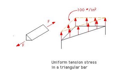
The equivalent force and centroid problem has many guises. In some instances, it is not force that is being integrated, but volume or area. For instance, suppose that we have bar with a triangular cross section that is under tension. If the bar is long (>> 4 times the width), we can assume that the tension is uniform throughout the cross section, mid-length along the member.This is known as a uniform stress distribution
3.2 Centre of Gravity
The center of gravity is a point where whole the weight of the body act is called center of gravity. As we know that every particle of a body is attracted by the earth towards its center with a magnitude of the weight of the body. As the distance between the different particles of a body and the center of the earth is the same, therefore these forces may be taken to act along parallel lines. A point may be found out in a body, through which the resultant of all such parallel forces acts. This point, through which the whole resultant (weight of the body acts, irrespective of its position, is known as center of gravity (briefly written as C.G). It may be noted that every body has one and only one center of gravity.
2.1 Centroid
The plane figures (like triangle, quadrilateral, circle etc.) have only areas, but no mass. The center of area of such figures is known as Centroid. The method of finding out the Centroid of a figure is the same as that of finding out the center of gravity of a body.
2.2 Axis of Reference
The center of gravity of a body is always calculated with referrer to some assumed axis known as axis of reference. The axis of reference, of plane figures, is generally taken as the lowest line of the figure for calculating y and the left line of the figure for calculating x.
3 Methods For Centre of Gravity of Simple Figures
The center of gravity (or Centroid) may be found out by any one of the following methods I. By geometrical considerations
2. By moments method
3. By graphical method
4 Center of Gravity by Geom etrical Considerations
The center of gravity of simple figures may be found out from the geometry of the figure
The center of gravity of plane f igure
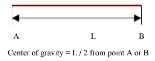
1. The center of g of uniform rod is at its middle point
2. The center of gravity of a rect angle is at a point, where its diagonals meet eac h other. It is also a mid point of the length as well a s the breadth of the rectangle as shown in fig
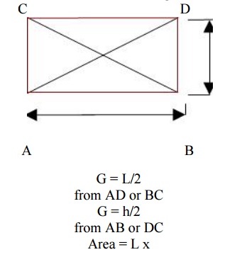
G = L/2 from AD or BC
G = h/2 from AB or DC
Area = L x
3. The center of gravity of a squa re is a point, where its diagonals meet each oth er. It is a mid point of its side as shown in fig
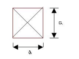
G = a/2 from any Area = 2x a
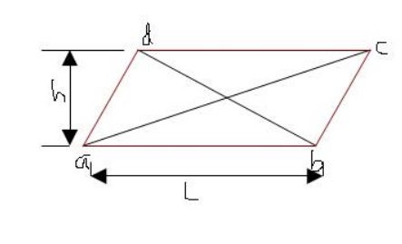
4. The center of gravity of a parallelogram is at a point, where its diagonals meet each other. It is also a mid point of the length as well as the height of the parallelogram as shown in fig
5 Centre of Gravity By Moments
The center of gravity of a body may also be found out by moments as discussed below. Consider a body of mass M whose center of gravity is required to be found out. Now divide the body into small strips of masses whose centers of gravity are known as shown in fig
Example1: Find the center of gravity of a 100 mm x 150 mm x 30 mm T-section. As shown in the fig
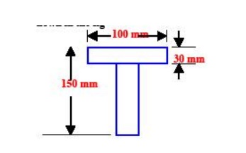
Given Height = 150 mm width = 100 mm thick ness = 30 mm
Required center of gravity = y =?
Working formulae y = Σa y or y = a1 y1 + a2y2 + a3 y 3 +………
Put in the working formula
y = Σa y = 531000 Y = 94.09 mm
Result center of gravity = 94.09 mm
6 Centre Of Gravity Of Solid Bodies
The center of gravity of solid bodies (such as hemisphere, cylinder, right circular solid cone etc) is found out in the same way as that of the plane figures. The only difference between the plane and solid bodies is that in the case of solid bodies we calculate volumes instead of areas
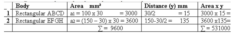
Problem 2: solid body formed by joining the base of a right circular cone of height H to the equal base of right circular cylinder of height h. calculate the distance of the center of gravity of the solid from its plane face when H = 120 mm and h = 30 mm
Given cylinder height = h = 30 mm
Right circular cone = H = 120 mm
Required center of gravity =?
Working formula
y = v 1 y 1 + v 2 /v1 + v2
Solution
Consider the cylinder
Volume of cylinder = π x r² x 30 = 94.286 r²
C.G of cylinder = y1 = 30/2 = 15mm
Now consider the right circular cone
Volume of cone = π/3 x r² x 120 = 377.143 r²
C.G of cone = y2 = 30 + 120/4 = 60 mm Put the values in the formula
y = v 1 y 1 + v 2 y 2 = 94.286 r² x 15 + 377.143 r² x60 v1 + v2 94.286 r² +377.143 r²
y = 40.7 mm
Result center of gravity = 40.7 mm
7 Centre of Gravity of Sections with Cut Out Holes
The center of gravity of such a section is found out by considering the main section; first as a complete one and then deducting the area of the cut out hole that is taking the area of the cut out hole as negative. Now substituting the area of the cut out hole as negative, in the general equation for the center of gravity, so the equation will become
x = a1 x1 - a2 x 2/ a1 - a2
Or
y = a1 y1 - a2 y 2/a1 - a2
8 Moment of Inertia
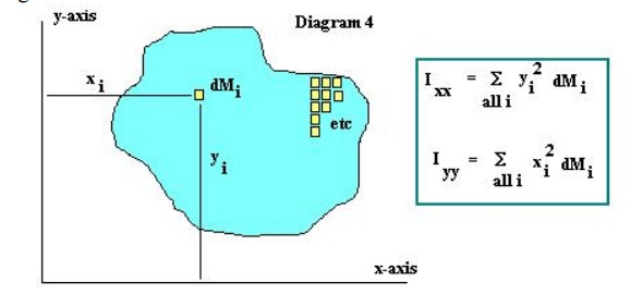
A second quantity which is of importance when considering beam stresses is the Moment of Inertia. Once again, the Moment of Inertia as used in Physics involves the mass of the object. The Moment of Inertia is obtained by breaking the object into very small bits of mass dM, multiplying these bits of mass by the square of the distance to the x (and y) axis and summing over the entire object. See Diagram
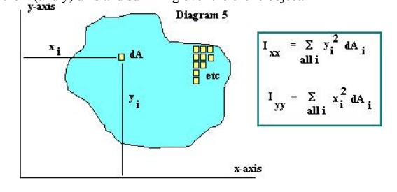
For use with beam stresses, rather than using the Moment of Inertia as discussed above, we will once again use an Area Moment of Inertia. This Area Moment of Inertia is obtained by breaking the object into very small bits of area dA, multiplying these bits of area by the square of the distance to the x (and y) axis and summing over the entire object.
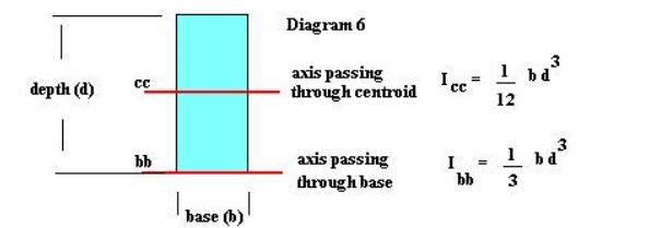
The actual value of the moment of inertia depends on the axis cho sen to calculate the moment of the inertia with respe ct to. That is, for a rectangular object, the mom ent of inertia about an axis passing through the ce ntroid of the rectangle is: I = 1/12 (base * d epth3) with units of inches4., while the moment of inertia with respect to an axis through the base of the rectangle is: I = 1/3 (base * depth3) in4. See Diagram 6. Note that the moment of inertia of any o bject has its smallest value when calculated with respe ct to an axis passing through the centroid of the object.
9 Parallel Axis Theorem
Moments of inertia abo ut different axis may calculated using the Parallel Axis Theorem,
which may be written: Ixx = Icc + Adc-x2 This says that the moment of inertia about any axis (Ixx) parallel to an axis through the ce ntroid of the object is equal to the moment of i nertia about the axis passing through the centroid (Icc ) plus the product of the area of the object and the distance between the two parallel axis (Adc-x2).We lastly take a moment to define several other concepts related to the Moment of Inertia.
Radius of Gyration: rxx = (Ixx/A )1/2 The radius of gyration is the distance from an axis which, if the entire area of the object were lo cated at that distance, it would result in the same moment of inertia about the axis that the object has.
Polar Moment of Inertia J = ∑(r2 )dA The polar moment of inertia is the su m of the produce of each bit of area dA and the radial distance to an origin squared. In a case as shown in belowthe polar moment of inertia in relate d to the x & y moments of inertia by: J = Ixx + Iyy.
One final comment - all the su mmations shown above become integrations as we let the dM's and dA's approach zero. And, whi le this is important and useful when calcula ting Centroids and Moments of Inertia, the summ ation method is just as useful for understanding the concepts involved.
Related Topics