Chapter: Software Design : Structured System Analysis and Design
Overview of Diagrams: Collaboration-Sequence, Class
Overview of Diagrams:
Collaboration-Sequence, Class
ü One Use
Case may include the functionality of another as part of its normal processing.
Generally, it is assumed that the included Use Case will be called every time
the basic path is run. An example may be to list a set of customer orders to
choose from before modifying a selected order - in this case the <list
orders> Use Case may be included every time the <modify order> Use
Case is run.
ü A Use
Case may be included by one or more Use Cases, so it helps to reduce
duplication of functionality by factoring out common behaviour into Use Cases
that are re-used many times.
ü One Use
Case may extend the behaviour of another - typically when exceptional
circumstances are encountered. For example, if before modifying a particular
type of customer order, a user must get approval from some higher authority,
then the <get approval> Use Case may optionally extend the regular
<modify order> Use Case.
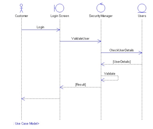
Sequence Diagrams
ü UML provides
a graphical means of depicting object interactions over time in Sequence
Diagrams. These typically show a user or actor, and the objects and components
they interact with in the execution of a use case. One sequence diagram
typically represents a single Use Case 'scenario' or flow of events.
ü Sequence
diagrams are an excellent way to document usage scenarios and to both capture
required objects early in analysis and to verify object usage later in design.
Sequence diagrams show the flow of messages from one object to another, and as
such correspond to the methods and events supported by a class/object.
ü The
diagram illustrated below shows an example of a sequence diagram, with the user
or actor on the left initiating a flow of events and messages that correspond
to the Use Case scenario. The messages that pass between objects will become
class operations in the final model.
Implementation Diagram
ü A Use
Case is a formal description of functionality the system will have when constructed.
An implementation diagram is typically associated with a Use Case to document
what design elements (eg. components and classes) will implement the Use Case
functionality in the new system. This provides a high level of traceability for
the system designer, the customer and the team that will actually build the
system. The list of Use Cases that a component or class is linked to documents
the minimum functionality that must be implemented by the component.
Relationships Between Use Cases
Use cases
could be organized using following relationships:
1. Generalization
2. Association
3. Extend
4. Include
Generalization Between Use Cases
ü Generalization
between use cases is similar to generalization between classes – child use case
inherits properties and behavior of the parent use case and may override the
behavior of the parent.
Notation:
Generalization
is rendered as a solid directed line with a large open arrowhead (same as
generalization between classes).
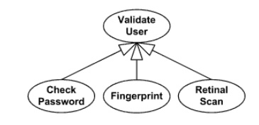
Generalization
between use cases
Association Between Use Cases
Use cases
can only be involved in binary
Associations. Two use cases specifying the same subject cannot be associated
since each of them individually describes a complete usage of the system.
Extend Relationship
Ø Extend is a directed relationship from an
extending use case to an extended
use case that specifies how and
when the behavior defined in usually supplementary (optional) extending use
case can be inserted into the behavior defined in the use case to be extended.
Ø Note: Extended use case is meaningful on its
own, independently of the extending use case, while the extending use case typically defines behavior that is not necessarily meaningful by itself.
Ø The
extension takes place at one or more extension points defined in the extended use case.
Ø The
extend relationship is owned by the
extending use case. The same extending use case can extend more than one use
case, and extending use case may itself be extended.
Ø Extend relationship between use cases is
shown by a dashed arrow with an open arrowhead from the extending use case
to the extended (base) use case. The
arrow is labeled with the keyword
«extend».
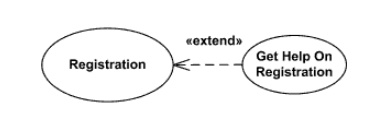
ü Registration use case is meaningful on its
own, and it could be extended with optional
Get Help On Registration use case
ü The condition of the extend relationship as
well as the references to the extension points are optionally shown in a Note attached to the corresponding
extend relationship.
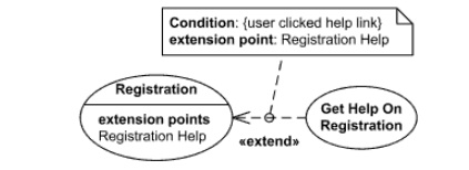
ü Registration
use case is conditionally extended by Get Help On Registration use case in
extension point Registration Help
Extension Point
An extension point is a feature of a use case which identifies
(references) a point in the behavior of the use case where that behavior can be
extended by some other (extending) use case, as specified by an extend
relationship.
ü Extension
points may be shown in a compartment of the use case oval symbol under the
heading extension points. Each
extension point must have a name,
unique within a use case. Extension points
are shown as text string according to the syntax: <extension point> ::= <name> [: <explanation>]
ü The
optional description is given usually as informal text, but can also be given
in other forms, such as the name of a state in a state machine, an activity in
an activity diagram, a precondition, or a postcondition.
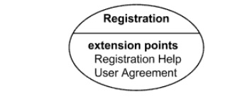
ü Registration
use case with extension points Registration Help and User Agreement
Extension points may be shown in a compartment of
the use case rectangle with ellipse icon
under the heading extension points.
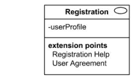
Extension
points of the Registration use case
shown using the rectangle notation
Include Relationship
ü An include relationship is a directed relationship between two use
cases, implying that the behavior of the required (not optional) included use case is inserted into the
behavior of the including (base) use
case. Including use case depends on the
addition of the included use case.
ü The
include relationship is intended to be used when there are common parts of the behavior of two or more use cases. This common
part is extracted into a separate use case to be included by all the base use
cases having this part in common.
Execution of the included use case is analogous to
a subroutine call or macro command in programming. All of the behavior of the
included use case is executed at a single location in the including use case
before execution of the including use case is resumed.
ü As the
primary use of the include relationship is to reuse common parts, including use cases are usually not complete by themselves but
dependent on the included use cases.
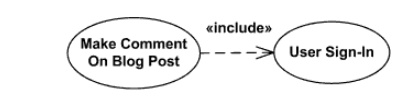
ü Include relationship between use cases is
shown by a dashed arrow with an open arrowhead from the including (base) use case to the included (common part) use
case. The arrow is labeled with the keyword «include».
Four Phases of Unified Process
ü The
Unified Process consists of cycles that may repeat over the long-term life of a
system. A cycle consists of four phases: Inception, Elaboration, Construction
and Transition. Each cycle is concluded with a release, there are also releases
within a cycle. Let's briefly review the four phases in a cycle:
Inception Phase - During
the inception phase the core idea is developed into a product vision. In this phase, we review and confirm our
understanding of the core business drivers. We want to understand the business
case for why the project should be attempted. The inception phase establishes
the product feasibility and delimits the project scope.
Elaboration Phase - During
the elaboration phase the majority of the Use Cases are specified in detail and the system architecture is
designed. This phase focuses on the "Do-Ability" of the project. We
identify significant risks and prepare a schedule, staff and cost profile for
the entire project.
Construction Phase - During
the construction phase the product is moved from the architectural baseline to a system complete enough
to transition to the user community. The
architectural
baseline grows to become the completed system as the design is refined into
code.
Transition Phase - In the
transition phase the goal is to ensure that the requirements have been met to the satisfaction of the
stakeholders. This phase is often initiated with a beta release of the
application. Other activities include site preparation, manual completion, and
defect identification and correction. The transition phase ends with a
postmortem devoted to learning and recording lessons for future cycles.
The primary purpose of this phase is to complete the most essential
parts of the project that are high risk and plan the construction phase. This
is the part of the project where technical risk is fully evaluated and/or
eliminated by building the highest risk parts of the project. During this phase
personnel requirements should be more accurately determined along with
estimated man hours to complete the project.
The complete cost and time frame of the project is more firmly
determined. During this phase how the system will work must be considered. Use
cases will help identify risks. Steps to take during this phase:
1. Complete
project plan with construction iterations planned with requirements for each
iteration.
2. 80% of
use cases are completed. Significant use cases are described in detail.
3. The
project domain model is defined. (Don't get bogged down)
4. Rank use
cases by priority and risk. Do the highest priority and highest risk use cases
first. Items that may be high risk:
-Overall system architecture especially when
dealing with communication between subsystems.
-Team
structure.
-Anything
not done before or used before such as a new programming language, or using the
unified/iterative
process for the first time.
5. Begin
design and development of the riskiest and highest priority use cases. There
will be an iteration for each high risk and priority use case.
6. Plan the
iterations for the construction phase. This involves choosing the length of the
iterations
and
deciding which use cases or parts of use cases will be implemented during each
iteration. Develop the higher priority and risk use cases during the first
iterations in the construction phase.
ü As was
done on a preliminary level in the previous phase, the value (priority) of use
cases and their respective risks must be more fully assessed in this phase.
This may be done be either assigning an number to each use case for both value
and risk. or categorize them by high, medium, or low value and risk. Time
required for each use case should be estimated to the man week. Do the highest
priority and highest risk use cases first.
ü Requirements
to be completed for this phase include:
1. Description
of the software architecture. Therefore most use cases should be done, activity
diagrams, state charts, system sequence diagrams, and the domain model should
be mostly complete.
2. A
prototype that overcomes the greatest project technical risk and has minimal
high priority functionality.
3. Complete
project plan.
4. Development
plan.
ü There may
be an elaboration phase for each high risk use case.
ü Considering
the various diagrams and charts to be created, when they are created, and the
best order to create them in, there seems to be a variety of opinions. This is
because in the real world there may be more than one correct solution and there
are no hard and fast rules that work everytime. In a way, this flexibility is a
strength of UML.
ü Some
documentation indicates that most use cases should be done before creating a
domain model and others indicate that the domain model can be built on a use
case by use case basis. A good compromise is to spend a short time on a brief
domain model during the elaboration phase, then enhance the domain model as
each use case is developed during the elaboration and construction phase
iterations.
ü Some
documentation indicates that activity diagrams and class diagrams should be
complete
before
the domain model is done. It is possible to create some of the diagrams and
charts (artifacts) in parallel with each otherCompletion of 80% of use case
diagrams.
1. Completion
of 80% of high level use case diagrams.
2. Completion
of expanded use case diagrams for major use cases only.
3. System
sequence diagrams for major use cases.
4.
Domain model (Don't get bogged down here with
details). Just get a good idea of concepts involved. Use use cases to create
the domain model. Any use case that strongly impacts the domain model should be
considered and concepts from that use case should be incorporated in the domain
model. The initial domain model may be drawn without lines and attributes to avoid
too much detail and determine important use cases. The domain model may be
refined later as the project analysis continues. If the system is large, domain
models should be done on a per use case basis.
5.
Optionally create a glossary of terms for concepts
to improve team communication.
ü After
this point the design part of the project begins (although more analysis is
done for each use case) and the following will be done in each iteration of the
elaboration and construction phases.
1. Operation
contracts based on domain model and use cases.
2. Collaboration
diagrams.
3. Class
diagrams.
4. Map class
and collaboration diagrams to code.
5. Update
the domain model but do not force it to the class diagrams. Considerations
during this project should be the following:
ü Consider
possible significant changes (down the road) to the system during analysis.
ü Regarding
system functional ability what do you expect to be able to change?
ü Elaboration
phase plans the necessary activities and required resources and specifies the features
and designing the architecture.
Things to
do: With the input of the use case model generated from the previous phase, we
transform it into a design model via an analysis model. In brief, both an
analysis model and a design model are structures made up of classifiers and a set of use-case
realizations that describe how this structure realizes the use cases.
Classifiers are, in general, "class-like" things.
ü The
analysis model is a detailed specification of the requirements and works as a
first cut at a design model, although it is a model of its own. It is used by
developers to understand precisely the use cases as described in the
requirements. The analysis model is different from the design model in that it
is a conceptual model rather than a blueprint of the implementation.
ü Class
Diagrams
ü Sequence
Diagrams
ü Collaboration
Diagrams
Exit
Criteria:
ü A detailed software development plan,
containing:
1. An
updated risk assessment,
2. A
management plan,
3. A
staffing plan,
4. A phase
plan showing the number and contents of the iteration
5. An iterative
plan, detailing the next iteration
6. The
development environment and other tools required
7. A test
plan
ü A
baseline vision, in the form of a set of evalution criteria for the final
product
ü Objective,
measurable evalution criteria for assessing the results of the initial
iterations of the construction phase
ü A domain
analysis model (80% complete), sufficient to be able to call the corresponding
architecture 'complete'.
ü A
software architecture description (stating constraints and limitations)
ü An executable
architectural baseline.
ü During
the Elaboration phase the project team is expected to capture a healthy
majority of the system requirements. However, the primary goals of Elaboration
are to address known risk factors and to establish and validate the system
architecture. Common processes undertaken in this phase include the creation of
use case diagrams, conceptual diagrams (class diagrams with only basic
notation) and package diagrams (architectural diagrams).
ü The
architecture is validated primarily through the implementation of an Executable
Architecture Baseline. This is a partial implementation of the system which
includes the core, most architecturally significant, components. It is built in
a series of small, timeboxed iterations. By the end of the Elaboration phase
the system architecture must have stabilized and the executable architecture
baseline must demonstrate that the architecture will support the key system
functionality and exhibit the right behavior in terms of performance, scalability
and cost.
ü The final
Elaboration phase deliverable is a plan (including cost and schedule estimates)
for the Construction phase. At this point the plan should be accurate and
credible, since it should be based on the Elaboration phase experience and
since significant risk factors should have been addressed during the
Elaboration phase.
ü The
Lifecycle Architecture Milestone marks the end of the Elaboration phase.
Related Topics