Chapter: civil : Applied Hydraulic Engineering: Pumps
Operation of Pumps in Series and Parallel
Operation of Pumps in
Series and Parallel
Pumps are chosen for particular requirement. The requirements
are not constant as per example the pressure required for flow through a piping
system. As flow increases, the pressure required increases. In the case of the
pump as flow increases, the head decreases. The operating condition will be the
meeting point of the two curves representing the variation of head required by
the system and the variation of head of the pump. This is shown in Figure.
The operating condition decides about the capacity of the pump
or selection of the pump. If in a certain setup, there is a need for increased
load; either a completely new pump may be chosen. This may be costlier as well
as complete revamping of the setup. An additional pump can be the alternate
choice. If the head requirement increases the old pump and the new pump can
operate in series.
In case more flow is required the old pump and the new pump
will operate in parallel. There are also additional advantages in two pump
operation. When the Pump-load characteristics load is low one of the pump can
operate with a higher efficiency when the load increases then the second pump
can be switched on thus improving part load efficiency. The characteristics of
parallel operation is depicted in Figure
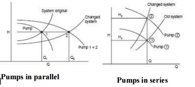
1 Pumps in parallel
The original requirement was Q1 at H1. Pump 1
could satisfy the same and operating point is at when the flow requirement and
the system characteristic is changed such that Q2 is required at head H1,
then two pumps of similar characteristics can satisfy the requirement.
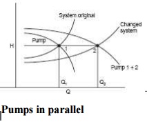
Providing a flow volume of Q2 as head H1. It is
not necessary that similar pumps should be used. Suitable control system for
switching on the second pump should be used in such a case. When the head
requirement is changed with flow volume being the same, then the pumps should
work in series. The characteristics are shown in Figure.
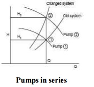
2 Pumps in series
The flow
requirement is Q. Originally head requirement was H1 met by the
first pump alone. The new requirement is flow rate Q and head H2.
This can be met by adding in series the pump2, which meets this requirement. It
is also possible to meet changes in both head and flow requirements by the use
of two pumps. Suitable control system should be installed for such purposes.
Problem
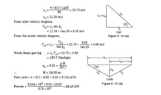
1:The
following details refer to a centrifugal pump. Outer diameter : 30 cm. Eye diameter
: 15 cm. Blade angle at inlet : 30 o . Blade angle at outlet : 25 o . Speed 1450
rpm. The flow velocity remains constant. The whirl at inlet is zero. Determine
the work done per kg. If the manometric efficiency is 82%, determine the
working head. If width at outlet is 2cm, determine the power o = 76%.
3 Minimum
Speed For Starting The Centrifugal Pump
N=(120
?manVw2 D)/(?(D22-D 2)
1
Where ?man
- manometric
efficiency
V -Whirl at out let of the
turbine D2 - diameter of impeller at out let
4 Net Positive Suction
Head (NPSH)
The pump manufacturer's specified
margin of suction pressure above the boiling point of the liquid being pumped,
is required to prevent cavitation. This pressure is called the 'Net Positive
Suction Head' pressure (NPSH).
In order to ensure that a NPSH
pressure is maintained, the Available NPSH should be higher than that required.
The NPSH depends on the height and density of the liquid and the pressure above
it.
5.Cavitation
Cavitations is a problem
condition which may develop while a centrifugal pump is operating. This occurs
when a liquid boils inside the pump due to insufficient suction head pressure.
Low suction head causes a pressure below that of vaporization of the liquid, at
the eye of the impeller. The resultant gas which forms causes the formation and
collapse of 'bubbles' within the liquid. This, because gases cannot be pumped
together with the liquid, causes violent fluctuations of pressure within the
pump casing and is seen on the discharge gauge.
These
sudden changes in pressure cause vibrations which can result in serious
damage to
the pump and, of course, cause pumping inefficiency.
To
overcome cavitations:
1.
Increase suction pressure if possible.
2.
Decrease liquid temperature if possible.
3.
Throttle back on the discharge valve to decrease
flow-rate.
4.
Vent gases off the pump casing.
6.Multistage Pump
If
centrifugal pump consists of two or more impellers the pump is called
Multistage pump. To produce a high head impellers are connected in series .To
produce high discharge impellers are connected in parallel.
Related Topics