Chapter: 11th Computer Science : Chapter 7 : Composition and Decomposition
Notations for Algorithms
Notations for Algorithms
We need a notation to represent
algorithms. There are mainly three different notations for representing
algorithms.
• A
programming language is a notation for expressing algorithms to be executed by
computers.
• Pseudo
code is a notation similar to programming languages. Algorithms expressed in
pseudo code are not intended to be executed by computers, but for communication
among people.
• Flowchart
is a diagrammatic notation for representing algorithms. They give a visual
intuition of the flow of control, when the algorithm is executed.
1. Programming language
A programming language is a
notation for expressing algorithms so that a computer can execute the
algorithm. An algorithm expressed in a programming language is called a
program. C, C++ and Python are examples of programming languages. Programming
language is formal. Programs must obey the grammar of the programming language
exactly. Even punctuation symbols must be exact. They do not allow the informal
style of natural languages such as English or Tamil. There is a translator
which translates the program into instructions executable by the computer. If
our program has grammatical errors, this translator will not be able to do the
translation.
2. Pseudo-code
Pseudo code is a mix of
programming-language-like constructs and plain English. This notation is not
formal nor exact. It uses the same building blocks as programs, such as
variables and control flow. But, it allows the use of natural English for
statements and conditions. An algorithm expressed as pseudo code is not for
computers to execute directly, but for human readers to understand. Therefore,
there is no need to follow the rules of the grammar of a programming language.
However, even pseudo code must be rigorous and correct. Pseudo code is the most
widely used notation to represent algorithms.
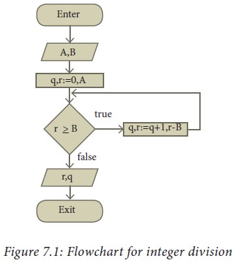
3. Flowcharts
Flowchart is a diagrammatic notation
for representing algorithms. They show the control flow of algorithms using
diagrams in a visual manner. In flowcharts, rectangular boxes represent simple
statements, diamond-shaped boxes represent conditions, and arrows describe how
the control flows during the execution of the algorithm. A flowchart is a
collection of boxes containing statements and conditions which are connected by
arrows showing the order in which the boxes are to be executed.
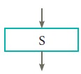
1. A statement is contained in a
rectangular box with a single outgoing arrow,which points to the box to be
executed next.
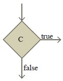
2. A condition is contained in a
diamond-shaped box with two outgoing arrows, labeled true and false. The true
arrow points to the box to be executed next if the condition is true, and the
false arrow points to the box to be executed next if the condition is false.
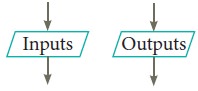
3. Parallelogram boxes represent
inputs given and outputs produced.
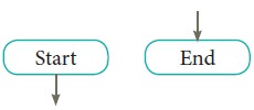
4. Special boxes marked Start and
the End are used to indicate the start and the end of an execution:
The flowchart of an algorithm to
compute the quotient and remainder after dividing an integer A by another
integer B is shown in Figure 7.1, illustrating the different boxes such as input,
output, condition, and assignment, and the control flow between the boxes. The
algorithm is explained in Example 7.4.
Flowcharts also have disadvantages.
(1) Flowcharts are less compact
than representation of algorithms in programming language or pseudo code.
(2) They obscure the basic
hierarchical structure of the algorithms. (3) Alternative statements and loops
are disciplined control flow structures. Flowcharts do not restrict us to
disciplined control flow structures.
Related Topics