Chapter: Embedded and Real Time Systems : Hardware Accelerates & Networks
Networks for Embedded Systems
NETWORKS
FOR EMBEDDED SYSTEMS:
Networks
for embedded computing span a broad range of requirements; many of those
requirements are very different from those for general-purpose networks. Some
networks are used in safety-critical applications, such as automotive control.
Some networks, such as those used in consumer electronics systems, must be very
inexpensive. Other networks, such as industrial control networks, must be
extremely rugged and reliable.
Several
interconnect networks have been developed especially for distributed embedded
computing:
The I2C
bus is used in microcontroller-based systems.
The
Controller Area Network (CAN) bus was developed for automotive electronics. It
provides megabit rates and can handle large numbers of devices.
Ethernet
and variations of standard Ethernet are used for a variety of control
applications.
1. The I2C Bus:
The I2C
bus [Phi92] is a well-known bus commonly used to link microcontrollers
into systems. It has even been used for the command interface in an MPEG-2
video chip [van97]; while a separate bus was used for high-speed video data,
setup information was transmitted to the on-chip controller through an I2C
bus interface.
I2C
is designed to be low cost, easy to implement, and of moderate speed (up to 100
KB/s for the standard bus and up to 400 KB/s for the extended bus). As a
result, it uses only two lines:
the serial
data line (SDL) for data and the serial clock line (SCL), which
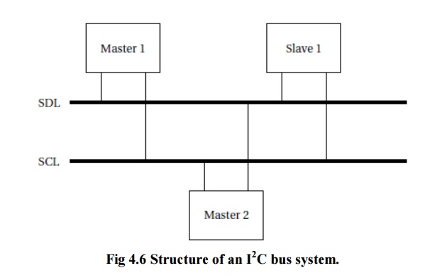
indicates when valid data are on the data line. Figure 4.6 shows the structure
of a typical I2C bus system.
Every
node in the network is connected to both SCL and SDL. Some nodes may be able to
act as bus masters and the bus may have more than one master. Other nodes may
act as slaves that only respond to requests from masters.
The basic
electrical interface to the bus is shown in Figure 4.7.The bus does not define
particular voltages to be used for high or low so that either bipolar or MOS
circuits can be connected to the bus.
Both bus
signals use open collector/open drain circuits.1 A pull-up resistor keeps the
default state of the signal high, and transistors are used in each bus device
to pull down the signal when a 0 is to be transmitted.
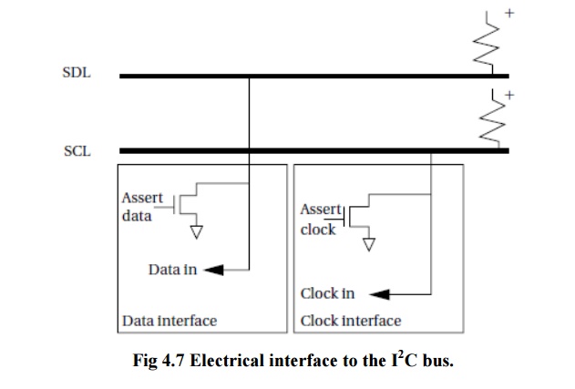
The Open
collector/open drain signaling allows several devices to simultaneously write
the bus without causing electrical damage. The open collector/open drain
circuitry allows a slave device to stretch a clock signal during a read from a
slave. The master is responsible for generating the SCL clock, but the slave
can stretch the low period of the clock (but not the high period) if necessary.
The I2C
interface on a microcontroller can be implemented with varying percentages of
the functionality in software and hardware [Phi89]. As illustrated in Figure
4.8, a typical system has a 1-bit hardware interface with routines for byte
level functions.
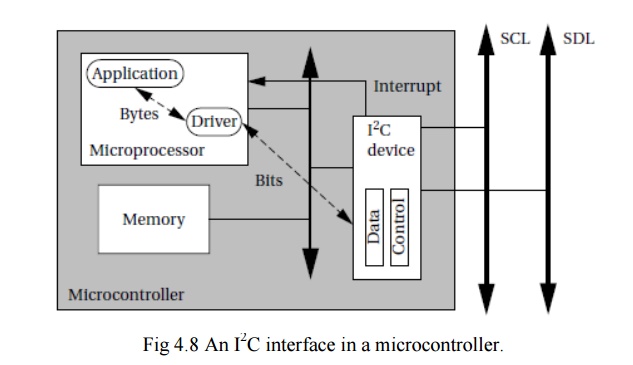
The I2C
device takes care of generating the clock and data. The application code calls
routines to send an address, send a data byte, and so on, which then generates
the SCL and SDL, acknowledges, and so forth.
One of
the microcontroller’s timers is typically used to control the length of bits on
the bus. Interrupts may be used to recognize bits. However, when used in master
mode, polled I/O may be acceptable if no other pending tasks can be performed,
since masters initiate their own transfers.
2. Ethernet
Ethernet
is very widely used as a local area network for general-purpose computing.
Because of its ubiquity and the low cost of Ethernet interfaces, it has seen
significant use as a network for embedded computing.
Ethernet
is particularly useful when PCs are used as platforms, making it possible to
use standard components, and when the network does not have to meet rigorous
real-time requirements.
The
physical organization of an Ethernet is very simple, as shown in Figure 8.14.
The network is a bus with a single signal path; the Ethernet standard allows
for several different implementations such as twisted pair and coaxial cable.
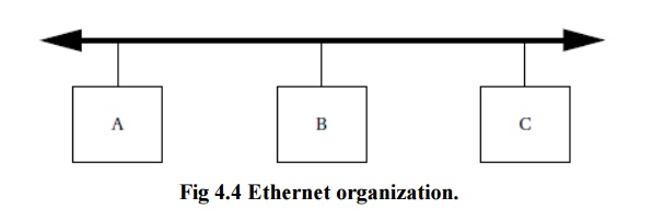
Unlike
the I2C bus,nodes on the Ethernet are not synchronized they can send
their bits at any time. I2C relies on the fact that a collision can
be detected and quashed within a single bit time thanks to synchronization.
But since
Ethernet nodes are not synchronized, if two nodes decide to transmit at the
same time, the message will be ruined. The Ethernet arbitration scheme is known
as Carrier
Sense Multiple Access with Collision Detection (CSMA/CD).
3. Field bus
Manufacturing
systems require networked sensors and actuators. Field bus
(http://www.fieldbus.org) is a set of standards for industrial control and
instrumentation systems.
The H1
standard uses a twisted-pair physical layer that runs at 31.25 MB/s. It is
designed for device integration and process control. The High Speed Ethernet
standard is used for backbone networks in industrial plants. It is based on the
100 MB/s Ethernet standard. It can integrate devices and subsystems.
Related Topics