Chapter: Mechanical : Dynamics of Machines : Mechanisms For Control
Mechanisms For Control
MECHANISMS FOR CONTROL
1 INTRODUCTION TO GOVERNOR:
A centrifugal governor is a specific type of governor that controls the speed of an engine by regulating the amount of fuel (or working fluid) admitted, so as to maintain a near constant speed whatever the load or fuel supply conditions. It uses the principle of proportional control.
It is most obviously seen on steam engines where it regulates the admission of steam into the cylinder(s). It is also found on internal combustion engines and variously fuelled turbines, and in some modern striking clocks.
![]()
2 PRINCIPLE OF WORKING:
Power is supplied to the governor from the engine's
output shaft by (in this instance) a belt or chain (not shown) connected to the
lower belt wheel. The governor is connected to a throttle valve that regulates
the flow of working fluid (steam) supplying the prime mover (prime mover not
shown). As the speed of the prime mover increases, the central spindle of the
governor rotates at a faster rate and the kinetic energy of the balls
increases. This allows the two masses on lever arms to move outwards and
upwards against gravity. If the motion goes far enough, this motion causes the
lever arms to pull down on a thrust bearing, which moves a beam linkage, which
reduces the aperture of a throttle valve. The rate of working-fluid entering
the cylinder is thus reduced and the speed of the prime mover is controlled,
preventing over speeding.
![]()
![]()
Mechanical stops may be used to limit the range of
throttle motion, as seen near the masses in the image at right.
The direction of the lever arm holding the mass will
be along the vector sum of the reactive centrifugal force vector and the
gravitational force.
![]()
![]()
3 CLASSIFICATION OF GOVERNORS:
Governors are classified based upon two different
principles. These are:
1. Centrifugal
governors
2. Inertia
governors
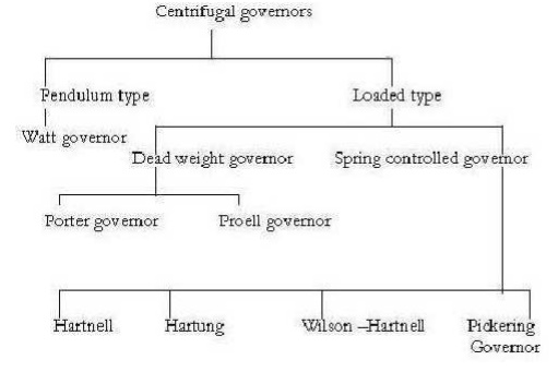
Centrifugal
governors are further classified as
(4) Height of governor
It is the vertical distance between the centre of
the governor halls and the point of intersection between the upper arms on the
axis of spindle is known as governor height. It is generally denoted by h.
(5) Sleeve lift
The vertical distance the sleeve travels due to
change in the equilibrium Speed is called the sleeve lift. The vertical
downward travel may be termed as Negative lift
(6) Isochronism
This is an extreme case of sensitiveness. When the
equilibrium speed is constant for all radii of rotation of the balls within the
working range, the governor is said to be in isochronism. This means that the
difference between the maximum and minimum equilibrium speeds is zero and the
sensitiveness shall be ininite.
(7) Stability
Stability is the ability to maintain a desired
engine speed without Fluctuating. Instability results in hunting or oscillating
due to over correction. Excessive stability results in a dead-beat governor or one
that does not correct sufficiently for load changes
(8) Hunting
The phenomenon of continuous fluctuation of the
engine speed above and below the mean speed is termed as hunting. This occurs
in over- sensitive or isochronous governors. Suppose an isochronous governor is
fitted to an engine running at a steady load. With a slight increase of load,
the speed will fall and the sleeve will immediately fall to its lowest
position. This shall open the control valve wide and excess supply of energy
will be given, with the result that the speed will rapidly increase and the
sleeve will rise to its higher position. As a result of this movement of the
sleeve, the control valve will be cut off; the supply to the engine and the
speed will again fall, the cycle being repeated indefinitely. Such a governor
would admit either more or less amount of fuel and so effect would be that the
engine would hunt.
4
SENSITIVENESS
A governor is said to be sensitive, if its change
of speed s from no Load to full load may be as small a fraction of the mean
equilibrium speed as possible and the corresponding sleeve lift may be as large
as possible.
Suppose
ω1 = max.
Equilibrium speed ω2 = min. equilibrium speed
ω =
mean equilibrium speed = (ω1+ ω2)/2
Therefore
sensitiveness = (ω1- ω2)/2
5 CHARACTERISTICS AND QUALITIES OF CENTRIFUGAL
GOVERNOR:
For satisfactory performance and working a
centrifugal governor should possess The following qualities.
a. On the
sudden removal of load its sleeve should reach at the top most position at
Once.
b. Its
response to the change of speed should be fast.
c. Its
sleeve should float at some intermediate position under normal operating
Conditions.
d. At the
lowest position of sleeve the engine should develop maximum power.
e. It should
have sufficient power, so that it may be able to exert the required force
At the
sleeve to operate the control & mechanism
6 WATT GOVERNOR:
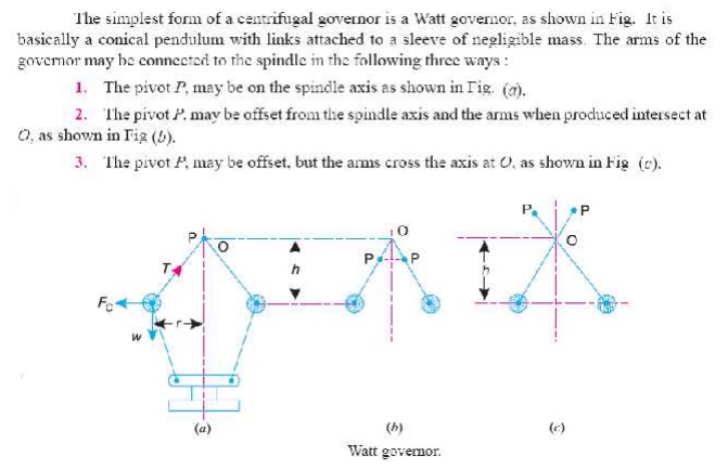
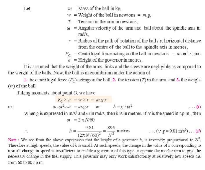
7 PORTER GOVERNOR:
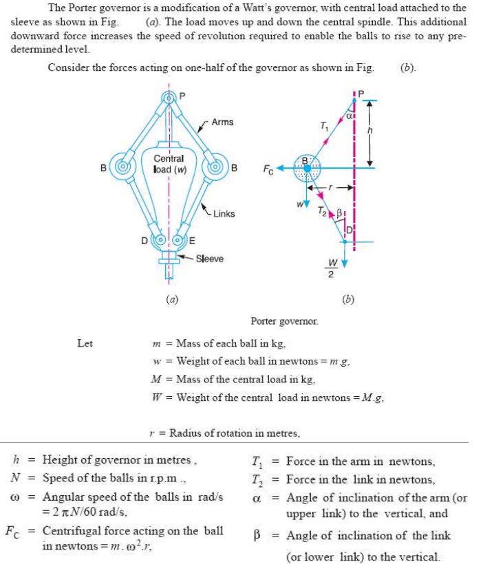
8 PROELL GOVERNOR:
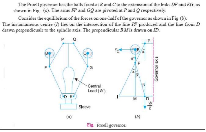
9 HARTNELL GOVERNOR:
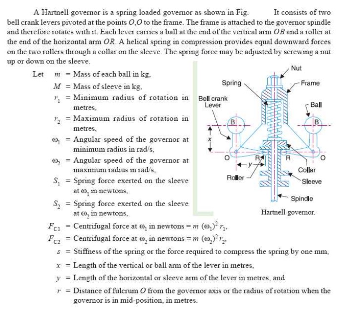
10 HARTUNG GOVERNOR:
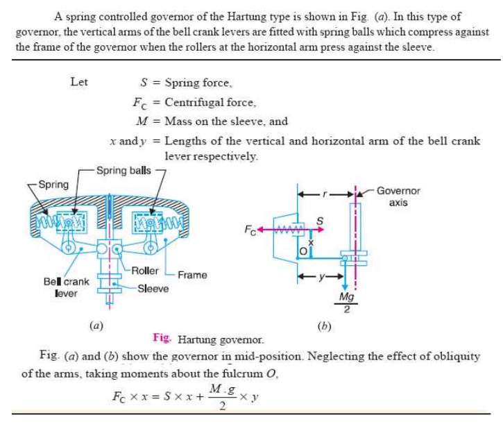
11 WILSON HARTNELL GOVERNOR:
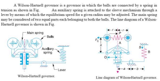
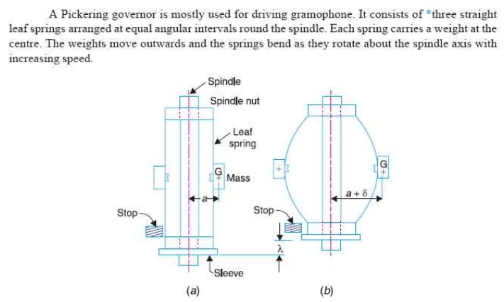
12 PICKERING GOVERNOR:
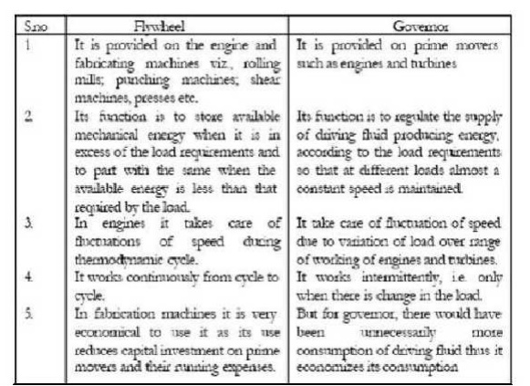
13 DIFFERENCE BETWEEN A FLYWHEEL AND A GOVERNOR:
14 GYROSCOPE AND ITS APPLICATIONS
(19) Gyroscope
A
gyroscope is a device for measuring or maintaining orientation, based on the
principles of conservation of angular momentum. A mechanical gyroscope is
essentially a spinning wheel or disk whose axle is free to take any
orientation. This orientation changes much less in response to a given external
torque than it would without the large angular momentum associated with the
gyroscope's high rate of spin. Since external torque is minimized by mounting
the device in gimbals, its orientation remains nearly fixed, regardless of any
motion of the platform on which it is mounted. Gyroscopes based on other
operating principles also Exit, such as the electronic, microchip-packaged MEMS
gyroscope devices found in consumer electronic devices, solid state ring
lasers, fiber optic gyroscopes and the extremely sensitive quantum gyroscope.
Applications of gyroscopes include navigation (INS) when magnetic compasses do
not work (as in the Hubble telescope) or are not precise enough (as in ICBMs)
or for the stabilization of flying vehicles like radio-controlled helicopters
or UAVs. Due to higher precision, gyroscopes are also used to maintain
direction in tunnel mining.
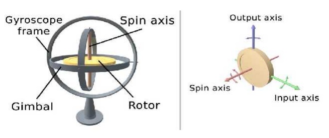
(20) Description and diagram:
Diagram of a gyro wheel. Reaction arrows about the
output axis (blue) correspond to forces applied about the input axis (green),
and vice versa. Within mechanical systems or devices, a conventional gyroscope
is a mechanism comprising a rotor journal led to spin about one axis, the
journals of the rotor being mounted in an inner gimbal or ring, the inner
gimbal is journal led for oscillation in an outer gimbal which is journal led
in another gimbal. So basically there are three gimbals. The outer gimbal or ring which is the
gyroscope frame is mounted so as to pivot about an axis in its own plane
determined by the support. This outer gimbal possesses one degree of rotational
freedom and its axis possesses none. The next inner gimbal is mounted in the gyroscope frame (outer gimbal) so as
to pivot about an axis in its own plane that is always perpendicular to the
pivotal axis of the gyroscope frame (outer gimbal). This inner gimbal has two
degrees of rotational freedom. Similarly, next innermost gimbal is attached to the inner gimbal which has three
degree of rotational freedom and its axis posses two. The axle of the spinning
wheel defines the spin axis. The rotor is journaled to spin about an axis which
is always perpendicular to the axis of the innermost gimbal. So, the rotor
possesses four degrees of rotational freedom and its axis possesses three. The
wheel responds to a force applied about the input axis by a reaction force
about the output axis.
The
behavior of a gyroscope can be most easily appreciated by consideration of the
front wheel of a bicycle. If the wheel is leaned away from the vertical so that
the top of the wheel moves to the left, the forward rim of the wheel also turns
to the left. In other words, rotation on one axis of the turning wheel produces
rotation of the third axis.
15 EFFECT
OF THE GYROSCOPIC
COUPLE ON AN
AERO PLANE
16 EFFECT OF GYROSCOPIC COUPLE
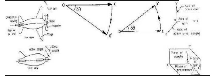
This
couple is, therefore, to raise the nose and dip the tail of the aero plane.
Notes
1. When
the aero plane takes a right turn under similar Conditions as discussed above,
the effect of the reactive Couple will be to dip the nose and raise the tail of
the aero plane.
2.When the
engine or propeller rotates in anticlockwise direction when viewed from the
rear or tail end and the aero plane takes a left turn, then the effect of
reactive gyroscopic couple will be to dip the nose and raise the tail of the
aero plane.
3.When the
aero plane takes a right turn under similar Conditions as mentioned in note 2
above, the effect of Reactive gyroscopic couple will be to raise the nose and
dip the of the aero plane.
4.When the
engine or propeller rotates in clockwise direction when viewed from the front
and the aero plane takes a left turn, then the effect of reactive gyroscopic
couple will be to raise the tail and dip the nose of the aero plane.
5. When the
aero plane takes a right turn under similar conditions as mentioned in note4
above, the effect of reactive gyroscopic couple will be to raise the nose and
dip the tail of the aero plane.
17 EFFECT OF GYROSCOPIC COUPLE ON
SHIP
The top and front views of a naval ship are shown
in fig. The fore end of the ship is called bow and the rear end is known as
stern or aft. The left hand and the right hand sides of the ship, when viewed
from the stern are called port and star board respectively. We shall now
discuss the effect of gyroscopic couple in the naval ship in the following
three cases:
1. Steering
2. Pitching,
and
3. Rolling
EFFECT OF GYROSCO PI C COUPLE O
N ANAVA LSHIP DU RI N G PI T CHI N G& STEERING
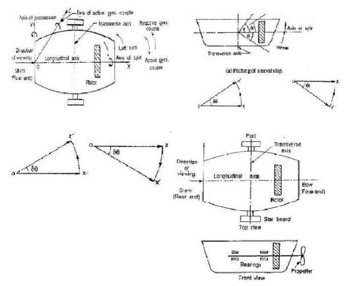
Steering is the turning of a complete ship in
a curve towards left or right, while it moves forward, considers the ship
taking a left turn, and rotor rotates in the clockwise direction when viewed
from the stern, as shown in Fig. below. The effect of gyroscopic couple on a
naval ship during steering taking left or right turn may be obtained in the
similar way as for an aero plane as discussed in Art.
When the rotor of the ship rotates in the
clockwise direction
when viewed from the stern, it will have its
angular momentum vector in the direction ox as shown in Fig. A1. As the ship
steers to the left, the active gyroscopic couple will change the angular
momentum vector from ox to ox’. The vector xx’ now represents the active
gyroscopic couple and is perpendicular to ox. Thus the plane of active gyroscopic
couple is perpendicular to xx’ and its direction in the axis OZ for left hand
turn is clockwise as shown in Fig below. The reactive gyroscopic couple of the
same magnitude will act in the opposite direction (i.e in anticlockwise
direction). The effect of this reactive gyroscopic couple is to raise the bow
and lower the stern.
Notes
1. When the ship steers to the right under
similar condition as discussed above, the effect of the reactive gyroscopic
couple, as shown in Fig. B1, will be to raise the stern and lower the bow.
2. When the rotor rotates in the anticlockwise
direction, when viewed from the stern and the ship is steering to the left,
then the effect of reactive gyroscopic couple will be to lower the bow and
raise the stern.
3. When the ship is steering to the right under
similar conditions as discussed in note 2 above, then the effect of reactive
gyroscopic couple will be to raise the bow and lower the stern.
4. When the rotor rotates in the clockwise
direction when viewed from the bow or fore end and the ship is steering to the
left, then the effect of reactive gyroscopic couple will be to raise the stern
and lower the bow.
5. When the ship is steering to the right under
similar conditions as discussed in note 4 above, then the effect of reactive
gyroscopic couple will be to raise the bow and lower the stern.
6. The effect of the reactive gyroscopic couple
on a boat propelled by a turbine taking left or right turn.
2 Effect of Gyro scop i c cou p le on a Naval S h i
p d u ri n g Rolling:
We know
that, for the effect of gyroscopic couple to occur, the axis of precession
should always be perpendicular to the axis of spin. If, however, the axis of
precession becomes parallel to the axis of spin, there will be no effect of the
gyroscopic couple acting on the body of the ship. In case of rolling of a ship,
the axis of precession (i.e. longitudinal axis) is always parallel to the axis
of spin for all positions. Hence, there is no effect of the gyroscopic couple
acting on the body of a ship.
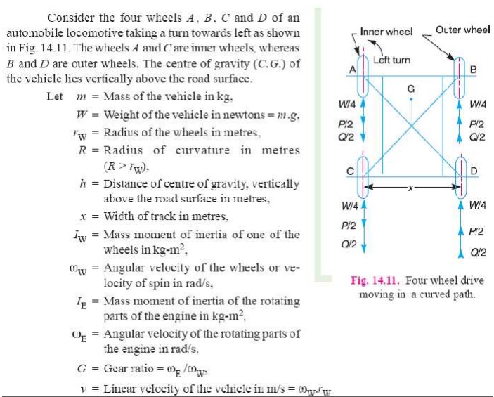
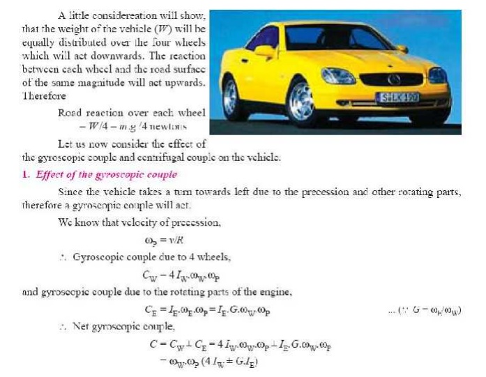
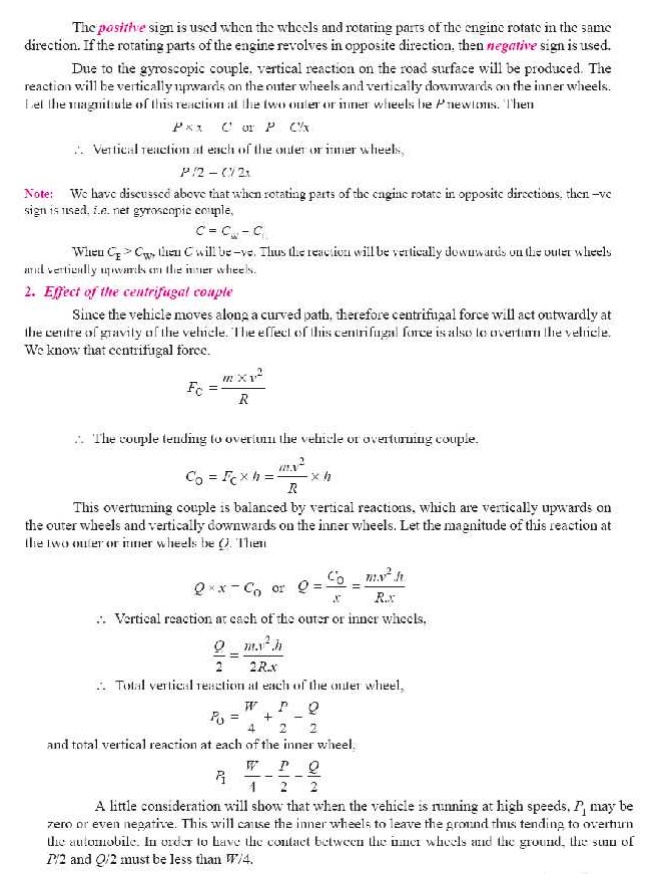
18 EFFECT OF GYROSCOPIC COUPLE ON A 4- WHEEL DRIVE
:
Related Topics