Chapter: Mechanical : Dynamics of Machines : Mechanisms For Control
Solved Problems: Mechanisms For Control
SOLVED PROBLEMS
1.(i) Explain the function of the proell governor
with the help of a neat sketch. Derive that relationship among the various
forces acting on the link. (12)
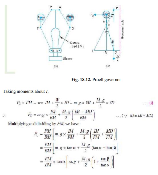
The Proell governor has the balls fixed at B and C to the extension of the links DF
and EG, as shown in Fig. 18.12 (a). The arms FP and GQ are pivoted at P and Q respectively.
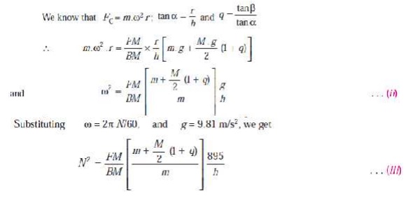
Consider the equilibrium of the forces on
one-half of the governor as shown in Fig. 18.12 (b). The instantaneous centre (I)
lies on the intersection of the line PF
produced and the line from D drawn
perpendicular to the spindle axis. The perpendicular B M is drawn on ID.
1 (ii).
What are centrifugal governors? how do
they differ from inertia governor? (4)
The
centrifugal governors are based on the balancing of centrifugal force on the
rotating balls by an equal and opposite radial force, known as the controlling
force
In
inertia governors the positions of the balls are affected by the rate of change
of speed. i.e., angular acceleration or retardation of the governor shaft. The
amount of displacement of governor balls is controlled by suitable springs and
the fuel supply to the engine is controlled by governor mechanism.
Though
the sensitiveness of the inertia governors is more, there is a practical
difficulty of balancing the inertia forces caused by the revolving parts of the
governor to the controlling force. Hence these governors are not preferred when
compared with the centifugal governors.
2. . A Proell governor has equal arms of length 300 m m. The upper and lower ends of the arms are pivoted on the axis of the governor. The extension arms of the lower links are each 80 mm long and parallel to the axis when the radii of rotation of the balls are 150 mm and 200 m m. The mass of each ball is 10 kg and the mass of the central load is 100 kg. Determine the range of speed of the governor.
Solution. Given : PF = DF = 300 mm ; BF = 80 mm ; m = 10 kg ; M = 100 kg
; r1 =
150 mm; r2 = 200 mm
First of all, let us find the minimum and
maximum speed of the governor. The minimum and maximum position of the governor
is shown in Fig. 18.13.
Let N1
= Minimum speed when radius of rotation, r1
= FG = 150 mm ; and
N2 =
Maximum speed when radius of rotation , r2 =
FG = 200 mm. From Fig. (a), we find that height of the governor,
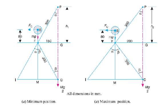
From Fig. (a),
we find that
sin α = sin β = 150 /
300 = 0.5 orα = β = 30°
and MD = FG =
150 mm = 0.15 m
FM
= FD cos β = 300 cos 30° = 260 mm =
0.26 m
IM = FM
tan α = 0.26
tan 30° = 0.15 m
BM
= BF + FM = 80 + 260 = 340 mm = 0.34 m
ID
= IM + MD = 0.15 + 0.15 = 0.3 m
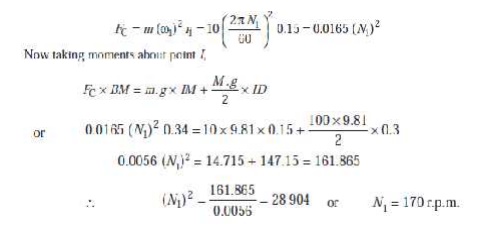
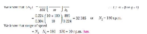
We know that centrifugal force,
h = PG = ( PF )
2– ( FG) 2 = (300) 2 – (200) 2 = 224 mm = 0.224 m
FM
= GD = PG = 224 mm = 0.224 m
B M = BF + FM = 80 + 224 = 304 mm = 0.304 m
3. The radius of rotation of the balls of a
Hartnell governor is 80 mm at the minimum speed of 300 r.p.m. Neglecting
gravity effect, determine the speed after the sleeve has lifted by 60 m m. Also
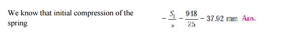
determine the initial compression of the spring, the governor effort and the
power.
The particulars of the governor
are given below:
Length of ball arm = 150 mm ;
length of sleeve arm = 100 mm ; mass of each ball = 4 kg ; and stiffness of the
spring = 25 N/m m.
Solution. Given : r1
= 80 mm = 0.08 m ; N1
= 300 r.p.m. or ω 1 = 2π × 300/60 = 31.42 rad/s ; h
= 60 mm = 0.06 m ; x = 150 mm = 0.15
m ; y = 100 mm = 0.1 m ; m = 4 kg ; s = 25 N/mm
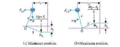
The minimum and maximum position of the governor
is shown in Fig. 18.36 (a) and (b) respectively. First of all, let us
find the maximum radius of rotation (r2).
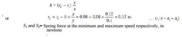
We know that lift of the sleeve,
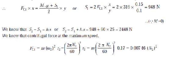
We know centrifugal force at the minimum speed,
FC1 = m
(ω 1)2 r1
= 4 (31.42)2 0.08 =
316 N
Now taking moments about the fulcrum O of the bell crank lever when in
minimum position as shown in Fig 18.36 (a).
The gravity effect is neglected, i.e. the moment due to the weight of
balls, sleeve and the bell crank lever arms is neglected.
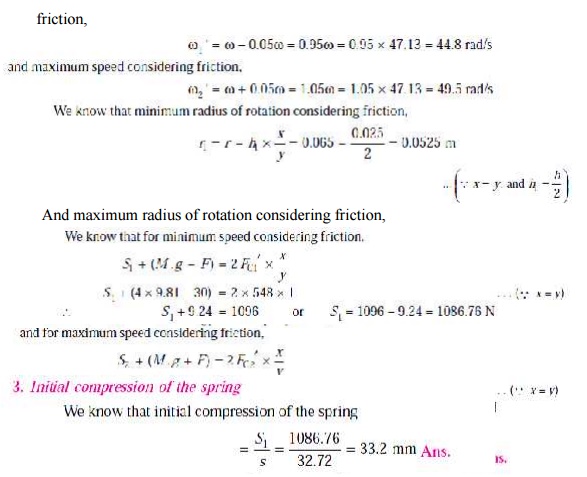
Initial compression of the spring
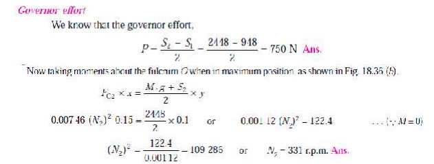
Governor power
We know that the governor power
= P × h =
750 × 0.06 = 45 N-m Ans.
3.
A Porter governor has all four arms 250 mm long.
The upper arms are attached on the axis of rotation and the lower arms are
attached to the sleeve at a distance of 30 m m from the axis. The mass of each
ball is 5 kg and the sleeve has a mass of 50 kg. The extreme radii of rotation
are 150 mm and 200 m m. Determine the range of speed of the governor.
Solution. Given : BP = BD = 250 mm ; DH
= 30 mm ; m = 5 kg ; M = 50 kg ; r1 = 150 mm ; r2 = 200 mm
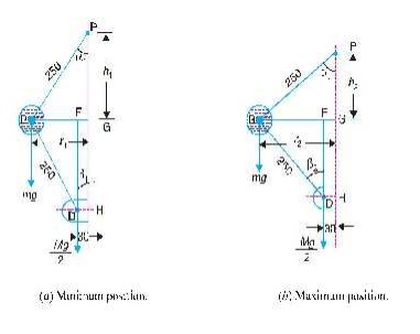
First of all, let us find the minimum and
maximum speed of the governor. The minimum and maximum position of the governor
is shown in Fig. 18.8 (a) and (b) respectively.
Let N1
= Minimum speed when r1 = BG = 150
mm ; and
N2
= Maximum speed when r2 = BG = 200 mm.
From Fig. 18.8 (a), we find that height of the
governor,
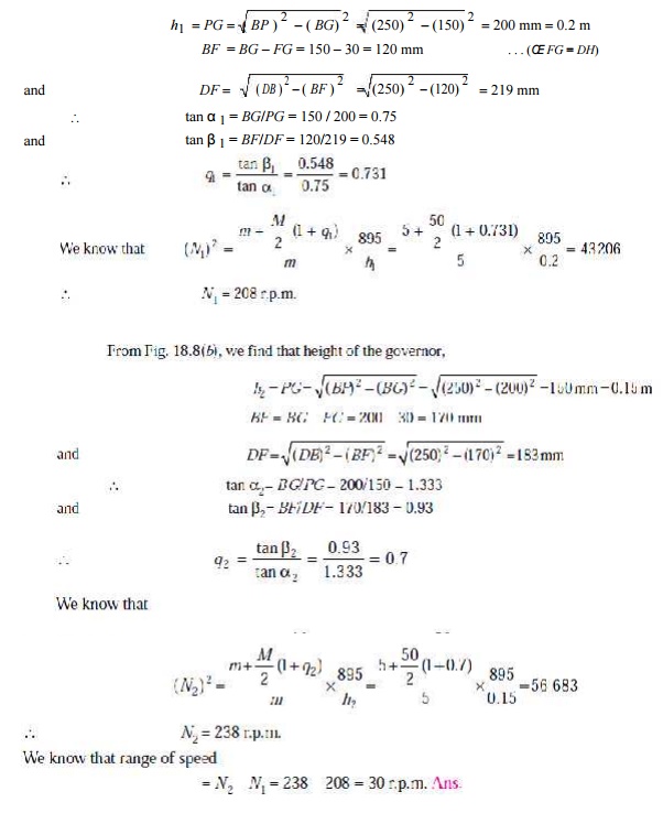
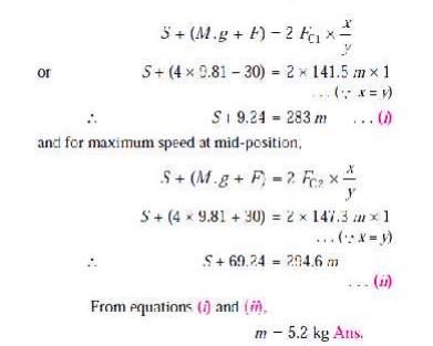
5. A spring loaded governor of the Hartnell type
has arms of equal length. The masses rotate in a circle of 130 mm diameter when the sleeve is in the
mid position and the ball arms are vertical. The equilibrium speed for this
position is 450 r.p.m., neglecting friction. The maximum sleeve movement is to
be 25 mm and the maximum variation of speed taking in account the friction to
be 5 per cent of the mid position speed. The mass of the sleeve is 4 kg and the
friction may be considered equivalent to 30 N at the sleeve. The power of the
governor must be sufficient to over-come the friction by one per cent change of
speed either way at mid-position. Determine, neglecting obliquity effect of
arms ; 1. The value of each rotating mass : 2. The spring stiffness in N/mm ;
and 3. The initial compression of spring.
Solution.
Given : x
= y ; d = 130 mm or r
= 65 mm = 0.065 m ; N
= 450 r.p.m. or ω = 2 π × 450/60
= 47.23 rad/s ; h = 25 mm = 0.025 m ;
M = 4 kg ; F = 30 N
1. Value of each rotating mass
Let m =
Value of each rotating mass in kg, and
S
= Spring force on the sleeve at mid position in newtons.
Since the change of speed at mid position to
overcome friction is 1 per cent either way (i.e. ± 1%), therefore
Minimum speed at mid position,
ω = ω – 0.01ω = 0.99ω = 0.99 ×
47.13 = 46.66 rad/s and maximum speed at mid-position,
ω 2 = ω + 0.01ω = 1.01ω = 1.01 × 47.13 = 47.6 rad/s ∴
Centrifugal force at the minimum speed,
FC1 = m (ω 1 )2
r = m (46.66)2 0.065 = 141.5 m N
and centrifugal force at the maximum speed,
FC2 = m (ω 2)2 r =
m (47.6)2 0.0065 =
147.3 m N We know that for minimum
speed at mid-position,
2. Spring stiffness in N/mm
Let s = Spring stiffness in N/mm.
Since the maximum variation of speed,
considering friction is ± 5% of the mid-position speed, therefore,
Minimum speed considering friction,
6. In an engine governor of the Porter type, the upper and lower arms are 200 m m and 250 mm respectively and pivoted on the axis of rotation. The mass of the central load is 15 kg, the mass of each ball is 2 kg and friction of the sleeve together with the resistance of the operating gear is equal to a load of 25 N at the sleeve. If the limiting inclinations of the upper arms to the vertical are 30° and 40°, find, taking friction into account, range of speed of the governor.
Solution . Given : BP = 200 mm = 0.2 m ; BD = 250 mm = 0.25 m ; M = 15 kg ; m = 2 kg ; F = 25 N ; α 1 = 30°; α 2 = 40°
First of all, let us find the minimum and
maximum speed of the governor.
The minimum and
maximum position of the governor is shown Fig. 18.7 (a) and (b) respectively.
Let N1
= Minimum speed, and N2 = Maximum
speed. From Fig. 18.7 (a), we find
that minimum radius of rotation,
r1 = BG =
BP sin 30° = 0.2 × 0.5 = 0.1 m Height of the governor, h1 = PG = BP cos 30° = 0.2 ×
0.866 = 0.1732 m
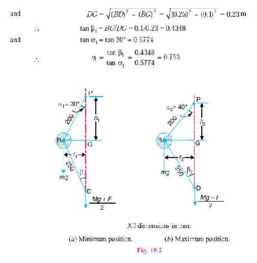
We know that when the sleeve moves downwards,
the frictional force (F) acts upwards
and the minimum speed is given by,
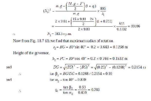
We know that when the sleeve moves upwards, the
frictional force (F) acts downwards
and the maximum speed is given by,
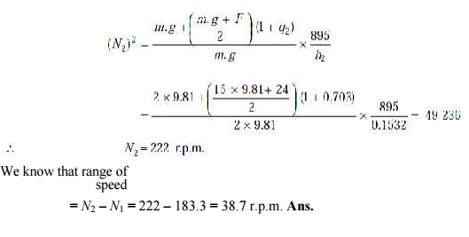
= N2 –
N1 = 222 – 183.3 = 38.7 r.p.m. Ans.
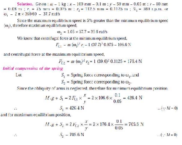
7.In a
spring loaded governor of the Hartnell type, the mass of each ball is 1kg,
length of vertical arm of the bell crank lever is 100 mm and that of the
horizontal arm is 50 m m. The distance of fulcrum of each bell crank lever is
80 mm from the axis of rotation of the governor. The extreme radii of rotation
of the balls are 75 mm and 112.5 m m. The maximum equilibrium speed is 5 per
cent greater than the minimum equilibrium speed which is 360 r.p.m. Find,
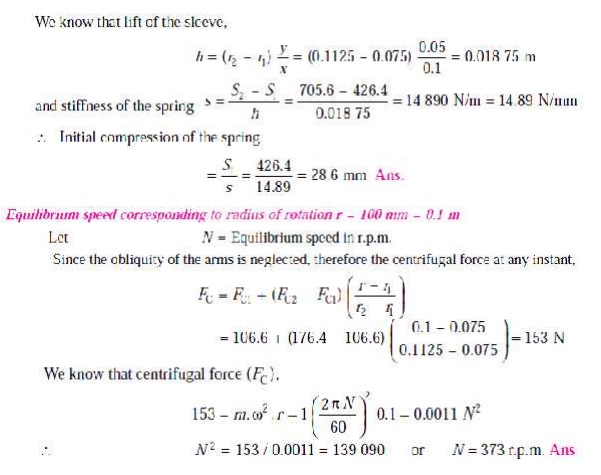
neglecting obliq-uity of arms, initial compression of the spring and
equilibrium speed corresponding to the radius of rotation of 100 m m.
1.
In a
governor of the Hartnell type, the mass of each ball is 1.5 kg and the lengths
of the vertical and horizontal arms of the bell crank lever are 100 mm and 50
mm respectively. The fulcrum of the bell crank lever is at a distance of 90 mm
from the axis of rotation. The maximum and minimum radii of rotation of balls
are 120 mm and 80 mm and the corresponding equilibrium speeds are 325 and 300
r.p.m. Find the stiffness of the spring and the equilibrium speed when the
radius of rotation is 100 mm.
[Ans.
18 kN/m, 315 r.p.m.]
A governor of the Hartnell type has equal balls
of mass 3 kg, set initially at a radius of 200 mm. The arms of the bell crank
lever are 110 mm vertically and 150 mm horizontally. Find : 1. the initial
compressive force on the spring, if the speed for an initial ball radius of 200
mm is 240 r.p.m. ; and 2. the stiffness of the spring required to permit a
sleeve movement of 4 mm on a fluctuation of 7.5 per
cent in the
engine speed. [Ans. 556 N ; 23.75 N/mm]
3. A four wheel trolley car of total mass 2000 kg
running on rails of 1 m gauge, rounds a curve of 25 m radius at 40 km / h. The
track is banked at 10°. The wheels have an external diameter of 0.6 m and each
pair of an axle has a mass of 200 kg. The radius of gyration for each pair is
250 mm. The height of C.G. of the car above the wheel base is 0.95 m. Allowing
for centrifugal force and gyroscopic couple action, determine the pressure on
each rail. [Ans. 4328 N ; 16 704 N]
4. 4. Each paddle wheel of a steamer have a mass of
1600 kg and a radius of gyration of 1.2 m. The steamer turns to port in a
circle of 160 m radius at 24 km / h, the speed of the paddles being 90 r.p.m.
Find the magnitude and effect of the gyroscopic couple acting on the steamer. [Ans. 905.6 N-m]
5. The rotor of the turbine of a yacht makes 1200
r.p.m. clockwise when viewed from stern. The rotor has a mass of 750 kg and its
radius of gyration is 250 mm. Find the maximum gyroscopic couple transmit-ted
to the hull (body of the yacht) when yacht pitches with maximum angular
velocity of 1 rad /s. What is the effect of this couple ? [Ans. 5892 N-m]
Related Topics