Chapter: Mechanical : Unconventional machining process : Mechanical Energy Based Processes
Mechanical Energy Based Processes
MECHANICAL
ENERGY BASED PROCESSES
MECHANICAL
PROCESSES
•
Abrasive
Jet Machining (AJM)
•
Abrasive
Water Jet Machining (AWJM)
•
Water
Jet Machining (WJM)
•
Ultrasonic
Machining (USM)
1
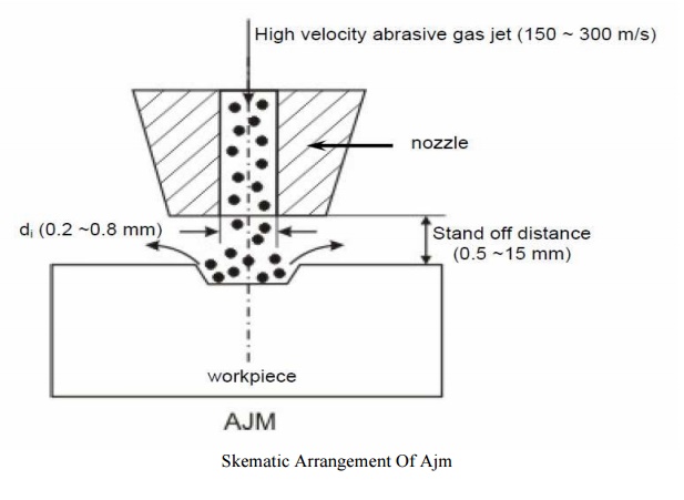
ABRASIVE JET MACHINING (AJM)
In
Abrasive Jet Machining (AJM), abrasive particles are made to impinge on the
work material at a high velocity. The high velocity abrasive particles remove
the material by micro-cutting action as well as brittle fracture of the work
material.
In AJM, generally, the abrasive
particles of around 50 μm grit size would impinge on the work material at
velocity of 200 m/s from a nozzle of I.D. of 0.5 mm with a standoff distance of
around 2 mm. The kinetic energy of the abrasive particles would be sufficient
to provide material removal due to brittle fracture of the work piece or even
micro cutting by the abrasives.
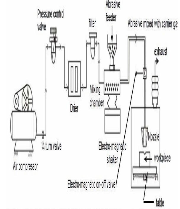
1. Process Parameters and Machining Characteristics
Abrasive: Material – Al2O3 / SiC /
glass beads
Shape – irregular / spherical
Size – 10 ~ 50 μm
Mass flow rate – 2 ~ 20 gm/min
Carrier gas: Composition – Air, CO2,
N2
Density – Air ~ 1.3 kg/m3
Velocity – 500 ~ 700 m/s Pressure –
2 ~ 10 bar
Flow rate – 5 ~ 30 lpm
Abrasive Jet : Velocity – 100 ~ 300
m/s
Mixing ratio – mass flow ratio of abrasive
to gas
Stand-off distance – 0.5 ~ 5 mm
Impingement
Angle – 60 ~ 90
Nozzle: Material – WC
Diameter – (Internal) 0.2 ~ 0.8 mm
Life – 10 ~ 300 hours
.2. Modeling of material removal
Material
removal in AJM takes place due to brittle fracture of the work material due to
impact of high velocity abrasive particles.
3. Modeling has been done with the following assumptions:
(i) Abrasives are spherical in shape and
rigid. The particles are characterized by the mean grit diameter
(ii) The kinetic energy of the abrasives
are fully utilized in removing material
(iii) Brittle materials are considered to
fail due to brittle fracture and the fracture volume is considered to be
hemispherical with diameter equal to choral length of the indentation
(iv) For ductile material, removal
volume is assumed to be equal to the indentation volume due to particulate
impact
2.
WATER JET MACHINING (WJM)
2.1. Introduction
Water
jet cutting can reduce the costs and speed up the processes by eliminating or
reducing expensive secondary machining process. Since no heat is applied on the
materials, cut edges are clean with minimal burr. Problems such as cracked edge
defects, crystallization, hardening, reduced wealdability and machinability are
reduced in this process.
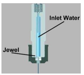
Water
jet technology uses the principle of pressurizing water to extremely high
pressures, and allowing the water to escape through a very small opening called
“orifice” or “jewel”. Water jet cutting uses the beam of water exiting the
orifice to cut soft materials. This method is not suitable for cutting hard
materials. The inlet water is typically pressurized between1300 – 4000 bars.
This high pressure is forced through a tiny hole in the je el, hich is
typically 0.18 to 0.4 mm in diameter. Picture of water jet chining process.
2.2. Applications
Water
jet cutting is mostly used to cut lower strength materials such as wood,
plastics and aluminium. When abrasives are added, (abrasive water jet cutting)
stronger materials such as steel and tool steel.
2.3. Advantages Of Water Jet Cutting
• There is no heat generated in
water jet cutting; which is especially useful for cutting tool steel and other
metals where excessive heat may change the properties of the material.
•
Unlike
machining or grinding, water jet cutting does not produce any dust or particles
that are harmful if inhaled.
•
Other
advantages are similar to abrasive water jet cutting
2.4. Disadvantages of water jet cutting
•
One
of the main disadvantages of water jet cutting is that a limited number of
materials can be cut economically.
•
Thick
parts cannot be cut by this process economically and accurately
•
Taper
is also a problem with water jet cutting in very thick materials. Taper is when
the jet exits the part at different angle than it enters the part, and cause
dimensional inaccuracy.
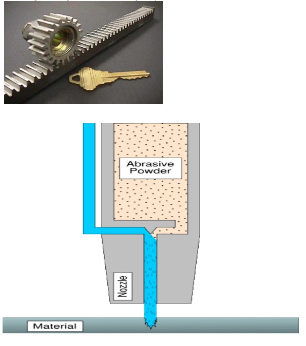
3. ABRASIVE WATER-JET MACHINING (AWJM)
3.1. Introduction
Abrasive
water jet cutting is an extended version of water jet cutting; in which the
water jet contains abrasive particles such as silicon carbide or aluminium
oxide in order to increase the material removal rate above that of water jet
machining. Almost a ny type of material ranging from hard brittle materials
such as ceramics, metals and glass to extremely soft materials such as foam and
rubbers can be cut by abrasive water jet cutting. The narrow cutting stream and
computer controlled movement enables this process to produce parts accurately
and efficiently. This machining process is especially ideal for cutting
materials that cannot be cut by laser or thermal cut. Metallic, non-metallic
and advanced composite materials of various thicknesses can be cut by this
process. This process is particularly suitable for heat sensitive materials
that cannot be machined by processes that produce heat while machining.
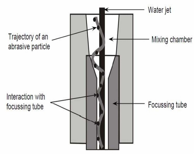
The schematic of abrasive water jet
cutting is shown in Figure 15 which is similar to water jet cutting apart from
some more features underneath the jewel; namely abrasive, guard and mixing
tube. In this process, high velocity water exiting the jewel creates a vacuum
which sucks abrasive from the abrasive line, which mixes with the water in the
mixing tube to form a high velocity beam of abrasives.
3.2.Applications
Abrasive water jet cutting is highly used in aerospace, automotive and electronics industries. In aerospace industries, parts such as titanium bodies for military aircrafts, engine components (aluminium, titanium, and heat resistant alloys), aluminium body parts and interior cabin parts are made using abrasive water jet cutting.
In
automotive industries, parts like interior trim (head liners, trunk liners, and
door panels) and fiber glass body components and bumpers are made by this
process. Similarly, in electronics industries, circuit boards and cable
stripping are made by abrasive water jet cutting.
.3.4.Advantages of abrasive water jet cutting
•
In
most of the cases, no secondary finishing required
•
No
cutter induced distortion
•
Low
cutting forces on work pieces
•
Limited
tooling requirements
•
Little
to no cutting burr
•
Typical
finish 125-250 microns
•
Smaller
kerf size reduces material wastages
•
No
heat affected zone
•
Localises
structural changes
•
No
cutter induced metal contamination
•
Eliminates
thermal distortion
•
No
slag or cutting dross
•
Precise,
multi plane cutting of contours, shapes, and bevels of any angle.
3.5 Limitations of abrasive water jet cutting
•
Cannot
drill flat bottom
•
Cannot
cut materials that degrades quickly with moisture
•
Surface
finish degrades at higher cut speeds which are frequently used for rough cuts
The
major disadvantage s of abrasive water jet cutting are high capital cost and
high noise levels during operation.
A
component cut by abrasive water jet cutting is shown in Figure .As it can be
seen, large parts can but cut with very narrow kerfs which reduces ma terial
wastages. The complex shape part made by abrasive water jet cutting
3.6.
Abrasive water jet cutting
•
WJM
- Pure
•
WJM
- with stabilizer
•
AWJM
– entrained – three phase –abrasive, water and air
•
AWJM
– suspended – two phase –abrasive and water o direct pumping
i. Indirect Pumping
ii. Bypass pumping
4.
ULTRASONIC MACHINING (USM)
4.1.
Introduction
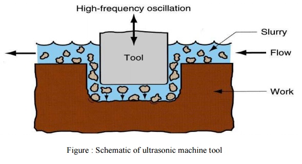
USM is mechanical material removal
process or an abrasive process used to erode holes or cavities on hard or
brittle work piece by using shaped tools, high frequency mechanical motion and
an abrasive slurry. USM offers a solution to the expanding need for machining
brittle materials such as single crystals, glasses and polycrystalline ceramics,
and increasing complex operations to provide intricate shapes and work piece
profiles. It is therefore used extensively in machining hard and brittle
materials that are difficult to machine by traditional manufacturing processes.
The hard particles in slurry are accelerated toward the surface of the work
piece by a tool oscillating at a frequency up to 100 KHz - through repeated
abrasions, the tool machines a cavity of a cross section identical to its own.
USM is primarily targeted for the
machining of hard and brittle materials (dielectric or conductive) such as
boron carbide, ceramics, titanium carbides, rubies, quartz etc. USM is a
versatile machining process as far as properties of materials are concerned.
This process is able to effectively machine all materials whether they are
electrically conductive or insulator.
For an effective cutting operation,
the following parameters need to be carefully considered:
•
The
machining tool must be selected to be highly wear resistant, such as
high-carbon steels.
•
The
abrasives (25-60 µm in dia.) in the (water-based, up to 40% solid volume)
slurry
Includes: Boron carbide, silicon
carbide and aluminum oxide.
Applications
The beauty of USM is that it can
make non round shapes in hard and brittle materials. Ultrasonically machined
non round-hole part is shown in Figure 11.
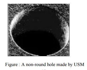
Figure : A non-round hole made by
USM
4.2Advantage
of USM
USM process is a non-thermal,
non-chemical, creates no changes in the microstructures, chemical or physical
properties of the work piece and offers virtually stress free machined
surfaces.
•
Any
materials can be machined regardless of their electrical conductivity
•
Especially
suitable for machining of brittle materials
•
Machined
parts by USM possess better surface finish and higher structural integrity.
•
USM
does not produce thermal, electrical and chemical abnormal surface
4.3.
Disadvantages of USM
•
USM
has higher power consumption and lower material-removal rates than traditional
Fabrication processes.
•
Tool
wears fast in USM.
•
Machining
area and depth is restraint in USM.
Related Topics