Chapter: Mechanical : Unconventional machining process : Mechanical Energy Based Processes
Abrasive Water Jet Machining (AWJM)
ABRASIVE WATER-JET MACHINING (AWJM)
3.1. Introduction
Abrasive water jet cutting is an extended version of water jet cutting; in which the water jet contains abrasive particles such as silicon carbide or aluminium oxide in order to increase the material removal rate above that of water jet machining. Almost a ny type of material ranging from hard brittle materials such as ceramics, metals and glass to extremely soft materials such as foam and rubbers can be cut by abrasive water jet cutting. The narrow cutting stream and computer controlled movement enables this process to produce parts accurately and efficiently. This machining process is especially ideal for cutting materials that cannot be cut by laser or thermal cut. Metallic, non-metallic and advanced composite materials of various thicknesses can be cut by this process. This process is particularly suitable for heat sensitive materials that cannot be machined by processes that produce heat while machining.
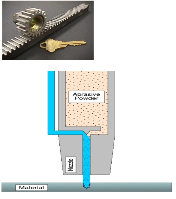
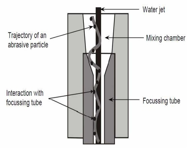
The schematic of abrasive water jet cutting is shown in Figure 15 which is similar to water jet cutting apart from some more features underneath the jewel; namely abrasive, guard and mixing tube. In this process, high velocity water exiting the jewel creates a vacuum which sucks abrasive from the abrasive line, which mixes with the water in the mixing tube to form a high velocity beam of abrasives.
3.2.Applications
Abrasive water jet cutting is highly used in aerospace, automotive and electronics industries. In aerospace industries, parts such as titanium bodies for military aircrafts, engine components (aluminium, titanium, and heat resistant alloys), aluminium body parts and interior cabin parts are made using abrasive water jet cutting.
In automotive industries, parts like interior trim (head liners, trunk liners, and door panels) and fiber glass body components and bumpers are made by this process. Similarly, in electronics industries, circuit boards and cable stripping are made by abrasive water jet cutting.
.3.4.Advantages of abrasive water jet cutting
• In most of the cases, no secondary finishing required
• No cutter induced distortion
• Low cutting forces on work pieces
• Limited tooling requirements
• Little to no cutting burr
• Typical finish 125-250 microns
• Smaller kerf size reduces material wastages
• No heat affected zone
• Localises structural changes
• No cutter induced metal contamination
• Eliminates thermal distortion
• No slag or cutting dross
• Precise, multi plane cutting of contours, shapes, and bevels of any angle.
3.5 Limitations of abrasive water jet cutting
• Cannot drill flat bottom
• Cannot cut materials that degrades quickly with moisture
• Surface finish degrades at higher cut speeds which are frequently used for rough cuts

The major disadvantage s of abrasive water jet cutting are high capital cost and high noise levels during operation.
A component cut by abrasive water jet cutting is shown in Figure .As it can be seen, large parts can but cut with very narrow kerfs which reduces ma terial wastages. The complex shape part made by abrasive water jet cutting
3.6. Abrasive water jet cutting
• WJM - Pure
• WJM - with stabilizer
• AWJM – entrained – three phase –abrasive, water and air
• AWJM – suspended – two phase –abrasive and water o direct pumping
i. Indirect Pumping
ii. Bypass pumping

Related Topics