Chapter: Measurements and Instrumentation : Storage and Display Devices
Magnetic Disk and Tape

Magnetic Disk and Tape
Magnetic Tape Recorder
Ø The magnetic tape recorders are used for high frequency signal recording.
Ø In these recorders, the data is recorded in a way that it can be reproduced in electrical form any time.
Ø Also main advantage of these recorders is that the recorded data can be replayed for almost infinite times.
Ø Because of good higher frequency response, these are used in Instrumentation systems extensively.
Basic Components of Tape Recorder
Following are the basic components of magnetic tape recorder
1. Recording Head
2. Magnetic Tape
3. Reproducing Head
4. Tape Transport Mechanism
5. Conditioning Devices
Recording Head
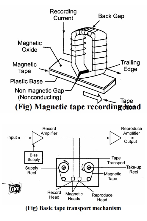
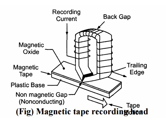
Ø The construction of the magnetic recording head is very much similar to the construction of a Transformer having a toroidal core with coil.
Ø There is a uniform fine air gap of 5µ m to 15µ m between the head and the magnetic tape.

Ø When the current used for recording is passed through coil wound around magnetic core, it produces magnetic flux.
Ø The magnetic tape is having iron oxide particles.
Ø When the tape is passing the head, the flux produced due to recording current gets linked with iron oxide part ices on th e magnetic tape and these particles get magnetized.
Ø This magnetization particle remain as it is, e vent Hough the magnetic tape leaves the gap.
Ø The act ual record ing ta kes place at the tra iling edg e of the air gap.
Ø Any signal is recorded in the form of the patterns.
Ø These magnetic patterns are dispersed anyw here along the length of mag netictape in accordance with the variation in recording current with respect to time.
Magnetic Tape
Ø The magnetic tape is made of thin sheet of tough and dimensionally stable plastic ribbon.
Ø One side of this plastic ribbon is coated by powdered iron oxide particles (Fe2O3) thick.
Ø The magnetic tape is wound around a reel.
Ø This tape is transferred from one reel to another.
Ø When the tape passes across air gap magnetic pattern is created in accordance with variation of recording current.
Ø To reproduce this pattern, the same tape with some recorded pattern is passed across another magnetic head in which voltage is induced.
Ø This voltage induced is in accordance with the magnetic pattern.
Reproducing Head
Ø The use of the reproducing head is to get the recorded data played back.
Ø The working of the reproducing head is exactly opposite to that of the recording head.
Ø The reproducing head detects the magnetic pattern recorded on the tape.
Ø The head converts the magnetic pattern back to the original electrical signal.
Ø In appearance, both recording and reproducing heads are very much similar.
Tape Transport Mechanism

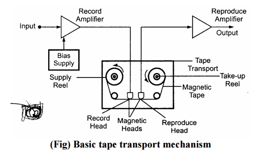
Ø The tape transport mechanism moves the magnetic tape along the recording head or reproducing head with a constant speed
Ø The tape transport mechanism must perform following tasks.
It must handle the tape without straining and wearing it.
It must guide the tape across magnetic heads with great precision.
It must maintain proper tension of magnetic tape.
It must maintain uniform and sufficient gap between the tape and heads.
Ø The magnetic tape is wound on reel.
Ø There are two reels; one is called as supply & other is called as take-up reel.
Ø Both the reels rotate in same direction.
Ø The transportation of the tape is done by using supply reel and take-up reel.
Ø The fast winding of the tape or the reversing of the tape is done by using special arrangements.
Ø The rollers are used to drive and guide the tape.
Conditioning Devices
Ø These devices consist of amplifiers and fitters to modify signal to be recorded.
Ø The conditioning devices allow the signals to be recorded on the magnetic tape with proper format.
Ø Amplifiers allow amplification of signal to be recorded and filters removes unwanted ripple quantities.
Principle of Tape Recorders
Ø When a magnetic tape is passed through a recording head, the signal to be recorded appears as some magnetic pattern on the tape.
Ø This magnetic pattern is in accordance with the variations of original recording current.
Ø The recorded signal can be reproduced back by passing the same tape through a reproducing head where the voltage is induced corresponding to the magnetic pattern on the tape.
Ø When the tape is passed through the reproducing head, the head detects the changes in the magnetic pattern i.e. magnetization.
Ø The change in magnetization of particles produces change in the reluctance of the magnetic circuit of the reproducing head, inducing a voltage in its winding.
Ø The induced voltage depends on the direction of magnetisation and its magnitude on the tape.
Ø The emf, thus induced is proportional to the rate of change of magnitude of magnetisation i.e. e N (dĭ / dt)
Where N = number of turns of the winding on reproducing head Ǽ = magnetic flux produced.
Suppose the signal to be recorded is Vm sin Ǚt. Thus, the current in the recording head and flux induced will be proportional to this voltage.
Ø It is given by e= k 1. Vm sin wt, where k1 = constant.
Ø Above pattern of flux is recorded on the tape. Now, when this tape is passed through the reproducing head, above pattern is regenerated by inducing voltage in the reproducing head winding.
Ø It is given by e= k2 ǙVm cos wt
Ø Thus the reproducing signal is equal to derivative of input signal
& it is proportional to flux recorded & frequency of recorded signal.
Methods of Recording
The methods used for magnetic tape recording used for instrumentation purposes are as follows:
i) Direct Recording
ii) Frequency Modulation Recording
iii) Pulse Duration Modulation Recording
For instrumentation purposes mostly frequency modulation recording is used. The pulse duration modulation recording is generally used in the systems for special applications where large number of slowly changing variables has to be recorded simultaneously.
Related Topics